
Ultrasound probe with integrated electronics

a technology of ultrasound probes and electronics, applied in the field of ultrasound imaging systems, can solve the problems of unfavorable use of ultrasound data in other contexts, unfavorable use of ultrasound data collection, and high cost, and achieve the effect of simplifying the cable requirements of the assembly

Inactive Publication Date: 2017-04-20
TERATECH CORP
View PDF4 Cites 14 Cited by
  • Summary
  • Abstract
  • Description
  • Claims
  • Application Information

AI Technical Summary

Benefits of technology

This patent is about an improved portable ulposes system that can be used with personal computers. The system is integrated, meaning it includes the control circuitry and beamforming circuitry in a single package, making it easier to use. The system can be used with a standard user computing device without needing expensive hardware modifications. It also includes safety features to ensure safe use. The method of controlling the system allows the operator to perform ultrasonic imaging operations with a single hand while controlling the system using a common operating position. Additionally, the patent describes a way for a third-party application to control the flow rate and amount of memory required for the system. This ensures that every frame is delivered to the third-party application without causing data loss or latency.

Problems solved by technology

These imaging systems tend to be unwieldy, expensive, and difficult to upgrade.
Further, since dedicated systems have specialized components, it is difficult to employ the gathered ultrasound data in other contexts, such as by downloading to another application for processing and / or operations which are unavailable on the native dedicated system.

Method used


Image

  • Ultrasound probe with integrated electronics
  • Ultrasound probe with integrated electronics
  • Ultrasound probe with integrated electronics

Examples


Embodiment Construction

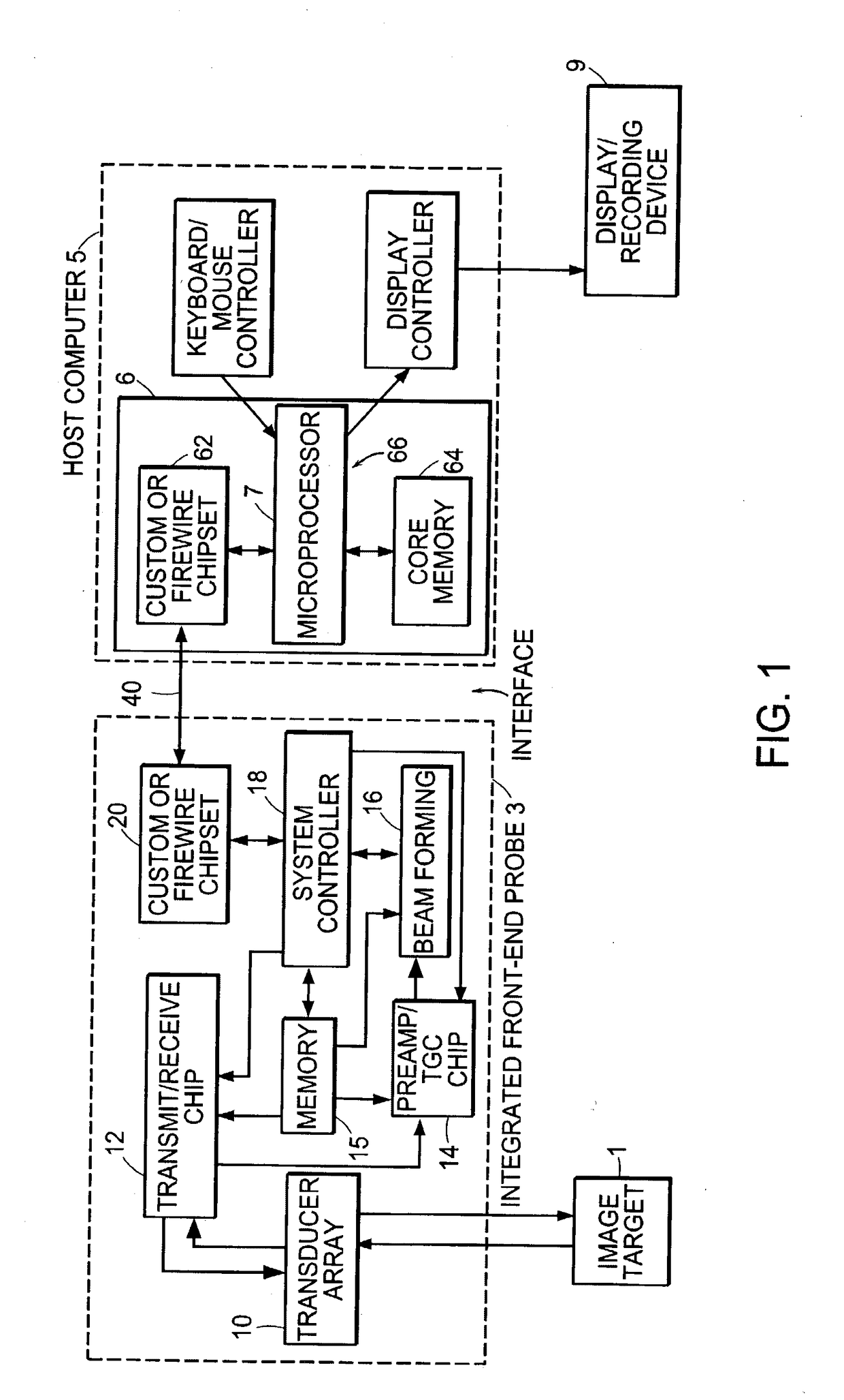
[0093]FIG. 1 is a schematic block diagram of an integrated probe system. Illustrated are a target object 1, a front-end probe 3, and a host computer 5, and a supplemental display / recording device 9. The front-end probe 3 integrates a transducer array 10 and control circuitry into a single hand-held housing. The control circuitry includes a transmit / receive module 12, a pre-amp / time-gain compensation (TGC) module 14, a charge domain processor (CDP) beamforming module 16, and a system controller 18. Memory 15 stores program instructions and data. The CDP beamformer integrated circuit 16 includes a computational capacity that can be used to calculate the delay coefficients used in each channel. The probe 3 interfaces with the host computer 5 over a communications link 40, which can follow a standard high-speed communications protocol, such as the FireWire (IEEE P1394 Standards Serial Interface) or fast (e.g., 200 Mbits / second or faster) Universal Serial Bus (USB 2.0) protocol. The stan...


PUM


Abstract

A hand-held ultrasound system includes integrated electronics within an ergonomic housing. The electronics includes control circuitry, beamforming and circuitry transducer drive circuitry. The electronics communicate with a host computer using an industry standard high speed serial bus. The ultrasonic imaging system is operable on a standard, commercially available, user computing device without specific hardware modifications, and is adapted to interface with an external application without modification to the ultrasonic imaging system to allow a user to gather ultrasonic data on a standard user computing device such as a PC, and employ the data so gathered via an independent external application without requiring a custom system, expensive hardware modifications, or system rebuilds. An integrated interface program allows such ultrasonic data to be invoked by a variety of such external applications having access to the integrated interface program via a standard, predetermined platform such as visual basic or c++.

Description

CROSS REFERENCES TO RELATED APPLICATIONS[0001]This application is a continuation of U.S. application Ser. No. 10 / 354,946 filed Jan. 30, 2003 which is a continuation-in-part of U.S. application Ser. No. 10 / 094,950 filed Mar. 11, 2002 which is a continuation-in-part of International Application PCT / US02 / 05764 filed on Feb. 22, 2002 which is a continuation-in-part of application Ser. No. 09 / 822,764 filed Mar. 30, 2001, which is a continuation-in-part of application Ser. No. 09 / 791,491 filed Feb. 22, 2001, which is a continuation-in-part of International Application No. PCT / US00 / 17236 filed on Jun. 22, 2000 which is a continuation-in-part of U.S. application Ser. No. 09 / 449,780 filed on Nov. 26, 1999 and claims the benefit of U.S. Provisional Application No. 60 / 140,430, filed on Jun. 22, 1999, the entire contents of the above applications being incorporated herein by reference in their entirety.BACKGROUND OF THE INVENTION[0002]Conventional ultrasound imaging systems typically include a ...

Claims


Application Information

Patent Timeline
Patent Type & Authority Applications(United States)
IPC IPC(8): A61B8/00A61B10/04A61B18/02G06F19/00A61M25/01A61N5/10A61B90/53G01S15/89A61B8/08A61B34/35G16H20/30G16H20/40G16H30/20G16H40/67G16H80/00
CPCA61B8/565A61B2503/40A61B8/4472A61B8/462A61B8/467A61B8/0866A61B8/0883A61B8/0891A61B8/485A61B10/04A61B18/02A61B34/35A61M25/0108A61N5/1039A61B8/0841A61B8/486A61B8/488A61B8/54A61B90/53A61B8/4455G01S15/899G06F19/3418A61B8/4427A61B8/546G01S7/5208A61B8/56A61B8/585A61B8/582G16H20/40G16H40/67G16H30/20G16H80/00G16H20/30A61B8/4405A61B8/4444A61B8/4477
Inventor BERGER, NOAHCHIANG, ALICE
Owner TERATECH CORP
Learn More