Ultrasound probe with integrated electronics

a technology of ultrasonic probes and electronics, applied in tomography, applications, instruments, etc., can solve the problems of significant torque that is administered by cables to the probe head, and achieve the effect of simplifying the cable requirements of the prob

Inactive Publication Date: 2005-03-22
TERATECH CORP
View PDF23 Cites 55 Cited by
  • Summary
  • Abstract
  • Description
  • Claims
  • Application Information

AI Technical Summary

Benefits of technology

In accordance with a preferred embodiment of the invention, further improvements in portable ultrasound medical imaging systems developed for use with personal computers are provided. In one embodiment the control circuitry and beamforming circuitry are localized in a hand-held probe. Such an integrated package simplifies the cable requirements of the probe, without adding significant weight to the probe.
A preferred embodiment of the invention can utilize certain safety features including circuits that check the power supply voltage level, that test every channel of the beamformer and assists in setting gain levels, that counts pulses per second and automatically shuts off the system to prevent over-radiating of the patient.
Another preferred embodiment of the invention employs the use of dedicated controls that the user can employ to perform specific tasks during a patient study. These controls are readily accessible and intuitive in use. These controls provide for freezing or unfreezing of the image on the display, for recording an image in electronic memory, to measure distances in two dimensions using a marker or caliper and a “set” function to fix two markers or calipers on screen, a track ball, touchpad or other manually manipulated element to control the marker, a time gain compensation control, such as 8 slide pots, to correct for sound attenuation in the body, scale or depth control to provide a zoom feature and for selection of focal zones.

Problems solved by technology

Because all of the circuitry is located remote from the probe, rather bulky cables tether the probe to the console processing unit.
Those cables administer a significant torque onto the probe head.

Method used


Image

  • Ultrasound probe with integrated electronics
  • Ultrasound probe with integrated electronics
  • Ultrasound probe with integrated electronics

Examples


Embodiment Construction

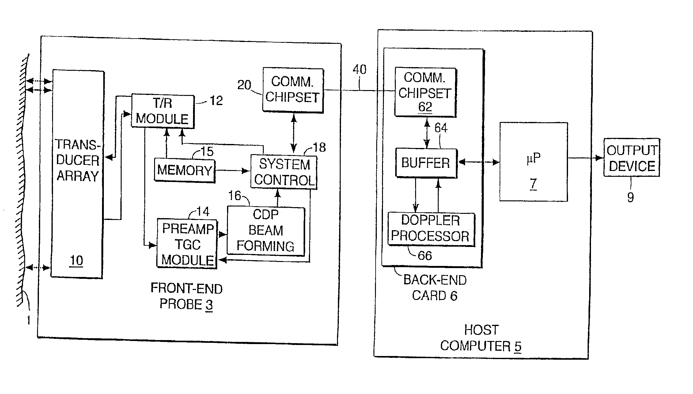
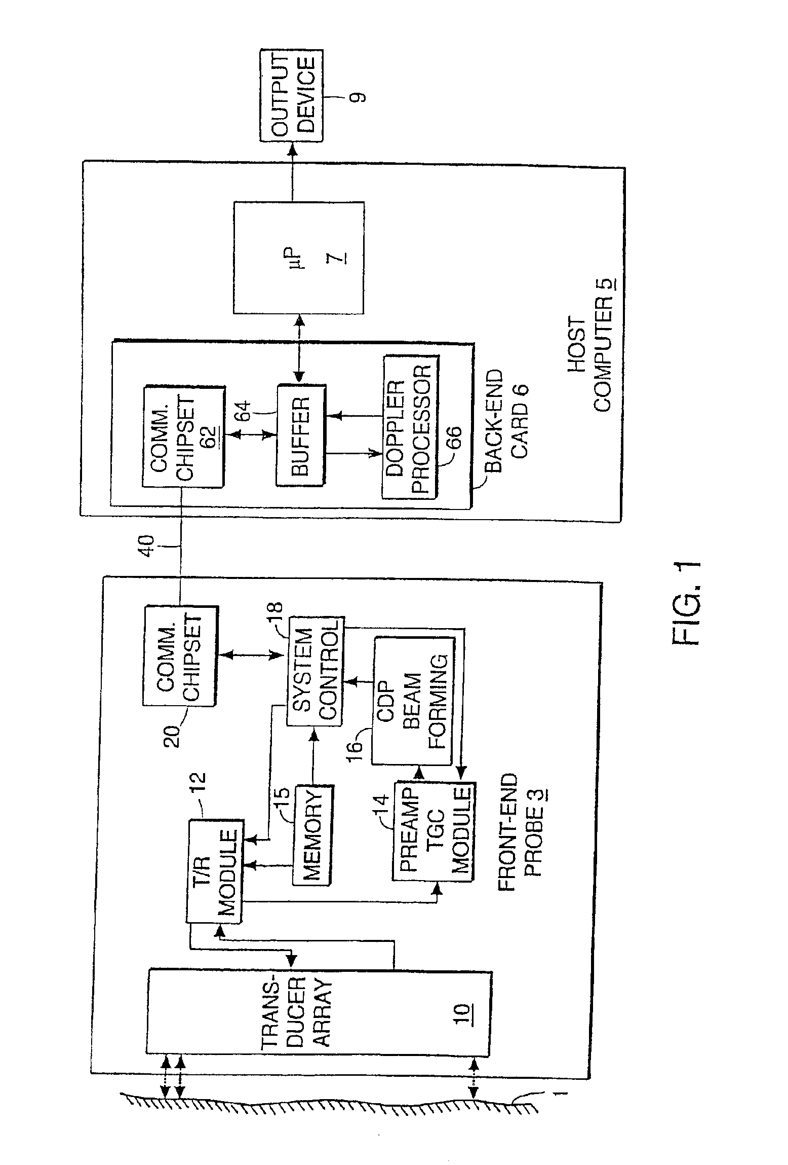
FIG. 1 is a schematic block diagram of an integrated probe system. Illustrated are a target object 1, a front-end probe 3, and a host computer 5. The front-end probe 3 integrates a transducer array 10 and control circuitry into a single hand-held housing. The control circuitry includes a transmit / receive module 12, a pre-amp / TGC module 14, a charge domain processor (CDP) beamforming module 16, and a system controller 18. Memory 15 stores program instructions and data. The CDP beamformer integrated circuit 16 includes a computational capacity that can be used to calculate the delay coefficients used in each channel. The probe 3 interfaces with the host computer 5 over a communications link 40, which can follow a standard high-speed communications protocol, such as the Fire Wire (IEEE 1394 Standards Serial Interface) or fast (e.g., 200 Mbits / second or faster) Universal Serial Bus (USB 2.0) protocol. The standard communication link to the personal computer operates at least at 100 Mbit...


PUM


Abstract

A hand-held ultrasound system includes integrated electronics within an ergonomic housing. The electronics includes control circuitry, beamforming and circuitry transducer drive circuitry. The electronics communicate with a host computer using an industry standard high speed serial bus.

Description

BACKGROUND OF THE INVENTIONConventional ultrasound imaging systems typically include a hand-held probe coupled by cables to a large rack-mounted console processing and display unit. The probe typically includes an array of ultrasonic transducers which transmit ultrasonic energy into a region being examined and receive reflected ultrasonic energy returning from the region. The transducers convert the received ultrasonic energy into low-level electrical signals which are transferred over the cable to the processing unit. The processing unit applies appropriate beam forming techniques to combine the signals from the transducers to generate an image of the region of interest.Typical conventional ultrasound systems include a transducer array each transducer being associated with its own processing circuitry located in the console processing unit. The processing circuitry typically includes driver circuits which, in the transmit mode, send precisely timed drive pulses to the transducer to...

Claims


Application Information

Patent Timeline
Patent Type & Authority Patents(United States)
IPC IPC(8): G01S15/89G01S15/00G01S7/521G01S7/52A61B8/00G10K11/34H01Q3/26H01Q25/00
CPCG01S7/52025G01S7/52063G01S7/52073G01S7/52074G01S7/52079G01S7/5208G01S7/52085G01S7/52095G01S15/892G01S15/8927G01S15/899G10K11/346H01Q3/26H01Q3/2682H01Q25/00G01S15/8915G01S7/52034A61B8/56G01S7/52055G01S15/8979G01S15/89
Inventor GILBERT, JEFFREY M.CHIANG, ALICE M.BROADSTONE, STEVEN R.MADISON, GARYHORST, ALBERT
Owner TERATECH CORP
Why Eureka
Try Eureka