Laser positioning navigation key frame selection method, medium, terminal and device

A laser positioning and key frame technology, applied in the field of robotics, can solve problems such as complex calculations, loss, and low computing efficiency, and achieve the effects of ensuring computing speed, improving efficiency, and improving effectiveness

Active Publication Date: 2020-03-17
SHANGHAI YOGO ROBOTICS CO LTD
View PDF3 Cites 3 Cited by
  • Summary
  • Abstract
  • Description
  • Claims
  • Application Information

AI Technical Summary

Problems solved by technology

There are many ways to select a key frame, such as whether the number of frames from the previous key frame is enough, select a key frame every fixed frame number, the effect is not good, and when the movement is very slow, a large number of similar keys will be selected Frames are redundant, and many important frames are lost when the movement is fast; whether the distance from the nearest key frame is far enough, such as creating a new key frame when the displacement or angle change relative to the previous key frame exceeds a certain threshold, If this method scans back and forth against the same object, a large number of similar key frames will appear; the key frame is selected according to the number and proportion of new feature points contained in the key frame. The calculation of this method is relatively complicated and the calculation efficiency is low.

Method used


Image

  • Laser positioning navigation key frame selection method, medium, terminal and device
  • Laser positioning navigation key frame selection method, medium, terminal and device
  • Laser positioning navigation key frame selection method, medium, terminal and device

Examples


Embodiment Construction

[0042] In order to make the object, technical solution and beneficial technical effects of the present invention clearer, the present invention will be further described in detail below in conjunction with the accompanying drawings and specific embodiments. It should be understood that the specific implementations described in this specification are only for explaining the present invention, not for limiting the present invention.

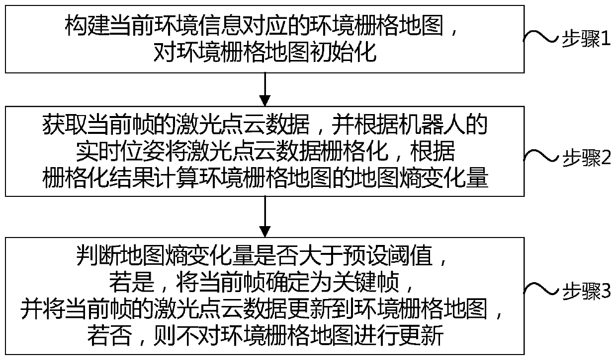
[0043] figure 1 It is a schematic flow chart of a key frame selection method for laser positioning and navigation provided in Embodiment 1 of the present invention, as shown in figure 1 shown, including the following steps:

[0044]Step 1, constructing an environmental grid map corresponding to the current environmental information, and initializing the environmental grid map; each cell in the environmental grid map contains at least a variable visits and a variable n, and the variable visits represents the current cell The number of times the ce...


PUM


Abstract

The invention discloses a laser positioning navigation key frame selection method, a medium, a terminal and a device. The accurate position of the robot is estimated in the mapping process; rasterizing laser, calculating the sum of front and back variations of all cell entropies accessed by the laser beams and the map entropy change caused by the current laser rasterization is obtained; and whether the current laser is the key frame or not is determined according to the variation of the map entropy so that the effectiveness of key frame laser selection is improved under the condition of ensuring the operation speed, the redundancy of map feature information is not liable to generate, the efficiency of laser SLAM is improved and the method has important significance in practical application.

Description

【Technical field】 [0001] The invention relates to the field of robots, in particular to a key frame selection method, medium, terminal and device for laser positioning and navigation. 【Background technique】 [0002] SLAM (Simultaneous Localization and Mapping) is the core technology of mobile robot positioning and navigation, and its full name is simultaneous positioning and mapping. The SLAM problem can be described as: the robot starts to move from an unknown position in an unknown environment. During the movement process, according to the sensors carried by itself and the real-time map constructed, the real-time pose estimation is performed through the slam technology, and the map is continuously updated and expanded at the same time, gradually Build a complete map of your environment. The implementation of laser radar is called laser slam, and the implementation of camera is called visual slam. Laser slam does not need to update each frame of laser to the map during th...

Claims


Application Information

Patent Timeline
Patent Type & Authority Applications(China)
IPC IPC(8): G01C21/20
CPCG01C21/20Y02D30/70
Inventor 李国飞
Owner SHANGHAI YOGO ROBOTICS CO LTD
Why Eureka
Try Eureka