
Electronic expansion valve

A technology of electronic expansion valve and valve needle, which is applied in the direction of lifting valve, valve device, lighting and heating equipment, etc., which can solve the problems of high noise and achieve the effect of eliminating noise, avoiding shaking and eliminating thread gap

Active Publication Date: 2022-04-05
SUZHOU HUAYUE METAL
View PDF0 Cites 0 Cited by
  • Summary
  • Abstract
  • Description
  • Claims
  • Application Information

AI Technical Summary

Problems solved by technology

[0004] The invention provides an electronic expansion valve to solve the problem of high noise when the electronic expansion valve in the prior art is in use

Method used


Image

  • Electronic expansion valve
  • Electronic expansion valve
  • Electronic expansion valve

Examples


Embodiment Construction

[0025] Next, the technical solutions in the embodiments of the present invention will be described in connection with the drawings of the embodiments of the present invention, and it is understood that the described embodiments are merely the embodiments of the present invention, not all of the embodiments. The following description of at least one exemplary embodiment is actually illustrative only, and it is not necessary to use any limitation of the invention and its application or use. Based on the embodiments in the present invention, all other embodiments obtained without creative labor are not made in the premise of creative labor.

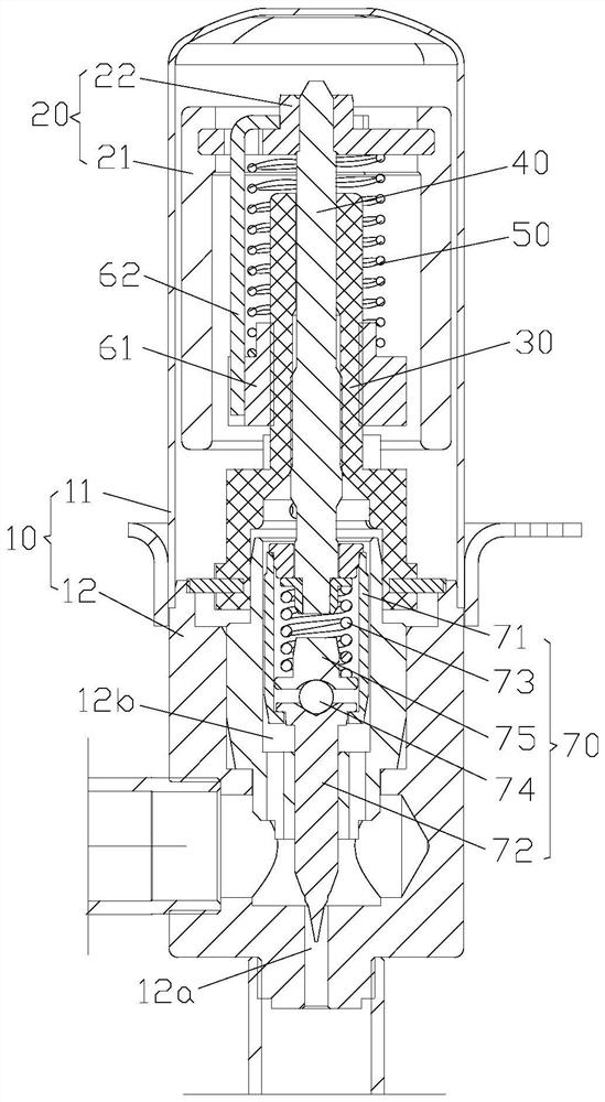
[0026] Such as figure 2 As shown, the embodiment of the present invention provides an electronic expansion valve comprising: a valve body 10, a rotor 20, a nut member 30, a screw 40, and a first pretensioning spring 50. Among them, the rotor 20, the nut member 30, the screw 40, and the first pretens spring 50 are each disposed in the valve body ...


PUM


Abstract

The invention provides an electronic expansion valve, which comprises: a valve body; a rotor arranged in the valve body; a nut part arranged in the valve body, and the rotor is sleeved on the outside of the nut part; a screw rod is arranged on the nut part , the screw rod is threadedly connected to the nut part, and the rotor is fixedly connected to the screw rod; the first preload spring is arranged in the valve body, the first preload spring is sleeved on the nut part, and the first end of the first preload spring is connected to the rotor, The second end of the first pre-tightening spring is arranged on the nut part, and the first pre-tightening spring is used for providing axial pre-tightening force to the rotor. The technical solution provided by the present application can solve the problem of high noise when the electronic expansion valve in the prior art is in use.

Description

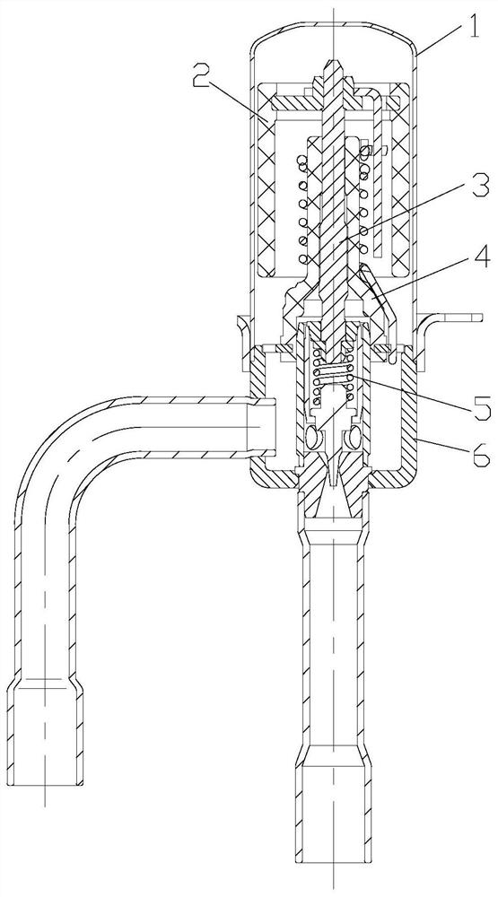
Technical field [0001] The present invention relates to the technical field of electronic expansion valve, and in particular, there is an electronic expansion valve. Background technique [0002] Such as figure 1 As shown, the currently existing electronic expansion valve includes a sleeve 1, a rotor 2, a screw 3, a nut member 4, a valve needle member 5, and a valve seat 6. The screw 3 is threaded with the nut member 4, and the screw 3 is inserted on the nut member 4, and the rotor 2 is sleeved on the nut member 4, and is fixedly connected to the screw 3, and the outer coil can cause the rotor 2 to drive the rotor 2. The screw 3 is lifted down, and the lower end of the screw 3 is coupled to the valve needle member 5, and the valve needle member 5 is lifted together by the screw 3 lifts to control fluid flow. [0003] In the prior art, since the screw 3 and the nut member 4 are threaded connections, the thread has a gap, so that the screw 3 sways when rotating relative to the nut ...

Claims


Application Information

Patent Timeline
Patent Type & Authority Patents(China)
IPC IPC(8): F16K1/02F16K1/32F25B41/345F25B41/34
CPCF16K1/02F16K1/32F25B41/31Y02B30/70
Inventor 罗高成许学飞裴俊峰
Owner SUZHOU HUAYUE METAL
Learn More