
Bird repelling device capable of adjusting light according to wind directions

A light and bird repellent technology, applied in animal repellents, applications, animal husbandry, etc., can solve problems such as short circuit of wires, reduced bird repellent effect, blind spot in the reflected light range, etc., to achieve enhanced stability and good bird repellent effect. , the effect of avoiding the possibility

Active Publication Date: 2020-04-28
山东方能电气制造有限公司
View PDF14 Cites 0 Cited by
  • Summary
  • Abstract
  • Description
  • Claims
  • Application Information

AI Technical Summary

Problems solved by technology

[0002] There are often birds nesting on the catenary of the railway. The long branches and bird excrement and other sundries when building the nest are in contact with the wires, which may easily cause a short circuit of the wires. Therefore, bird repellents are installed on the catenary. Commonly used The bird repellent is a wind-powered bird-repelling device installed in areas where birds are easy to nest. The traditional wind-powered bird-repelling device includes three reflective mirrors on the horizontal plane to reflect sunlight to the position where birds are easy to nest. The sunlight is vertical After being illuminated, the reflected light is concentrated in the lower horizontal direction, forming a small reflected light area, but there is a blind spot in the reflected light range, which basically has no function of dispersing the flying birds directly above, and due to the small reflection angle, some birds Humans can gradually adapt to this light after staying in the air for a period of time, resulting in a gradual decrease in the bird repelling effect. After long-term evolution, birds have become more accustomed to flying with the wind. hover over the nest position with the wind, and then gradually adapt to the light of the optical bird repellent. At present, there is no device for repelling birds based on this characteristic of birds.

Method used


Image

  • Bird repelling device capable of adjusting light according to wind directions
  • Bird repelling device capable of adjusting light according to wind directions
  • Bird repelling device capable of adjusting light according to wind directions

Examples


Embodiment Construction

[0019] The following will clearly and completely describe the technical solutions in the embodiments of the present invention with reference to the accompanying drawings in the embodiments of the present invention. Obviously, the described embodiments are only some, not all, embodiments of the present invention. Based on the embodiments of the present invention, all other embodiments obtained by persons of ordinary skill in the art without making creative efforts belong to the protection scope of the present invention.

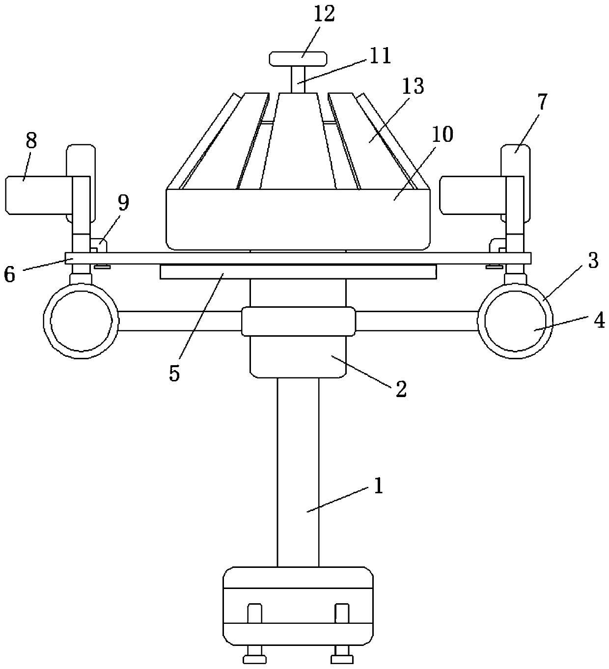
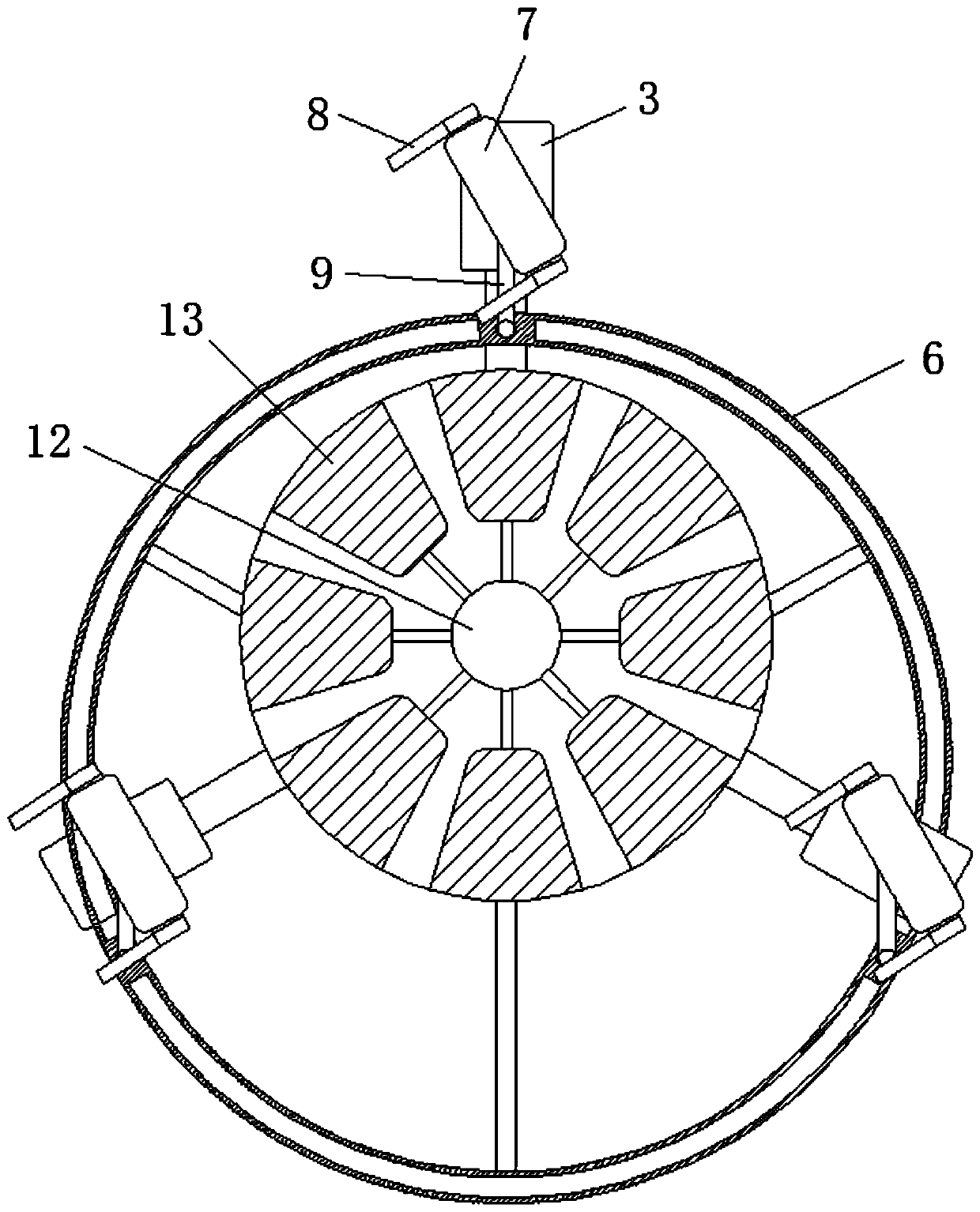
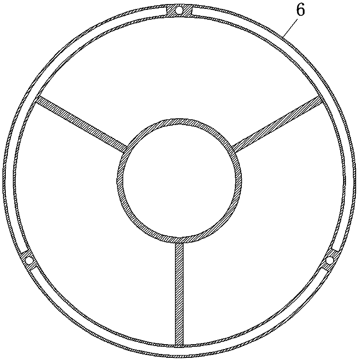
[0020] see Figure 1-5 , a bird repelling device for adjusting light according to the wind direction, comprising a support frame 1, a sleeve 2 is fixedly sleeved on the outside of the support frame 1, and three evenly distributed wind bowls 3 are movably sleeved on the outside of the sleeve 2, and the wind bowl 3 The interior of the sleeve 2 is fixedly inlaid with a concave reflector 4, and the outside of the sleeve 2 is fixedly sleeved with a support plate 5 ...


PUM


Abstract

A bird repelling device capable of adjusting light according to the wind direction comprises a supporting frame, a concave reflector is fixedly embedded in a wind bowl, a limiting ring is movably connected to the top of a supporting plate and on a sleeve, a vertical reflector is rotationally connected to the top of the wind bowl, and plane reflectors which are evenly distributed are movably hingedto the top of a base. A downward reflection light area is formed through the concave reflectors, birds are prevented from nesting on the lower contact net, an upward reflection light area is formed through the vertical reflectors and the plane reflectors to repel the birds passing through the upper space, the three vertical reflectors face the same direction through the limiting ring, and when the birds pass through the area along the wind, the reflected light directly irradiates the eyes of the birds, so that the birds are difficult to bear and quickly leave the area, the birds do not stop on the contact net below, and the possibility of bird nesting is avoided from the source.

Description

technical field [0001] The invention relates to the technical field of railway safety, in particular to a bird repelling device that adjusts light according to the wind direction. Background technique [0002] There are often birds nesting on the catenary of the railway. The long branches and bird excrement and other sundries when building the nest are in contact with the wires, which may easily cause a short circuit of the wires. Therefore, bird repellents are installed on the catenary. Commonly used The bird repellent is a wind-powered bird-repelling device installed in areas where birds are easy to nest. The traditional wind-powered bird-repelling device includes three reflective mirrors on the horizontal plane to reflect sunlight to the position where birds are easy to nest. The sunlight is vertical After being illuminated, the reflected light is concentrated in the lower horizontal direction, forming a small reflected light area, but there is a blind spot in the reflect...

Claims


Application Information

Patent Timeline
Patent Type & Authority Applications(China)
IPC IPC(8): A01M29/08
CPCA01M29/08
Inventor 陈景顺
Owner 山东方能电气制造有限公司
Learn More