Matching structure for drum plate and pipe body locking groove of telescopic baton

A telescopic technology with a matching structure, applied in the direction of batons, weapons without explosives, offensive equipment, etc., can solve the problems of shrinking the outer tube body cavity of the outer tube body, losing the locking effect, affecting the proper function of the telescopic baton, etc. achieve the effect of increasing friction

Pending Publication Date: 2020-04-28
常熟市吉宏精密机械有限公司
View PDF7 Cites 0 Cited by
  • Summary
  • Abstract
  • Description
  • Claims
  • Application Information

AI Technical Summary

Problems solved by technology

But in the actual use process, when the impact head of the rear tube body of the telescopic baton is subjected to a strong impact force, the center tube body drum butterfly will appear to exit the center tube body drum butterfly groove to the center of the center tube body cavity of the center tube body The direction of displacement tends to form a sliding surface between the middle tube body drum butterfly and the middle tube body drum butterfly groove. Following this sliding surface, the middle tube body drum butterfly can easily slide out of the middle tube body drum butterfly groove and lose its locking effect. Thereby the middle tube body is retracted into the outer tube body cavity of the outer tube body, which affects the due effect of the retractable baton

Method used


Image

  • Matching structure for drum plate and pipe body locking groove of telescopic baton
  • Matching structure for drum plate and pipe body locking groove of telescopic baton

Examples


Embodiment Construction

[0019] In order to understand the technical essence and beneficial effects of the present invention more clearly, the applicant will describe in detail the following examples, but the descriptions of the examples are not intended to limit the solutions of the present invention. Equivalent transformations that are only formal but not substantive should be regarded as the scope of the technical solution of the present invention.

[0020] In the following descriptions, all concepts related to the directionality or orientation of up, down, left, right, front and rear are taken as examples in the illustrated position state, and thus cannot be interpreted as the technology provided by the present invention. Program specific restrictions.

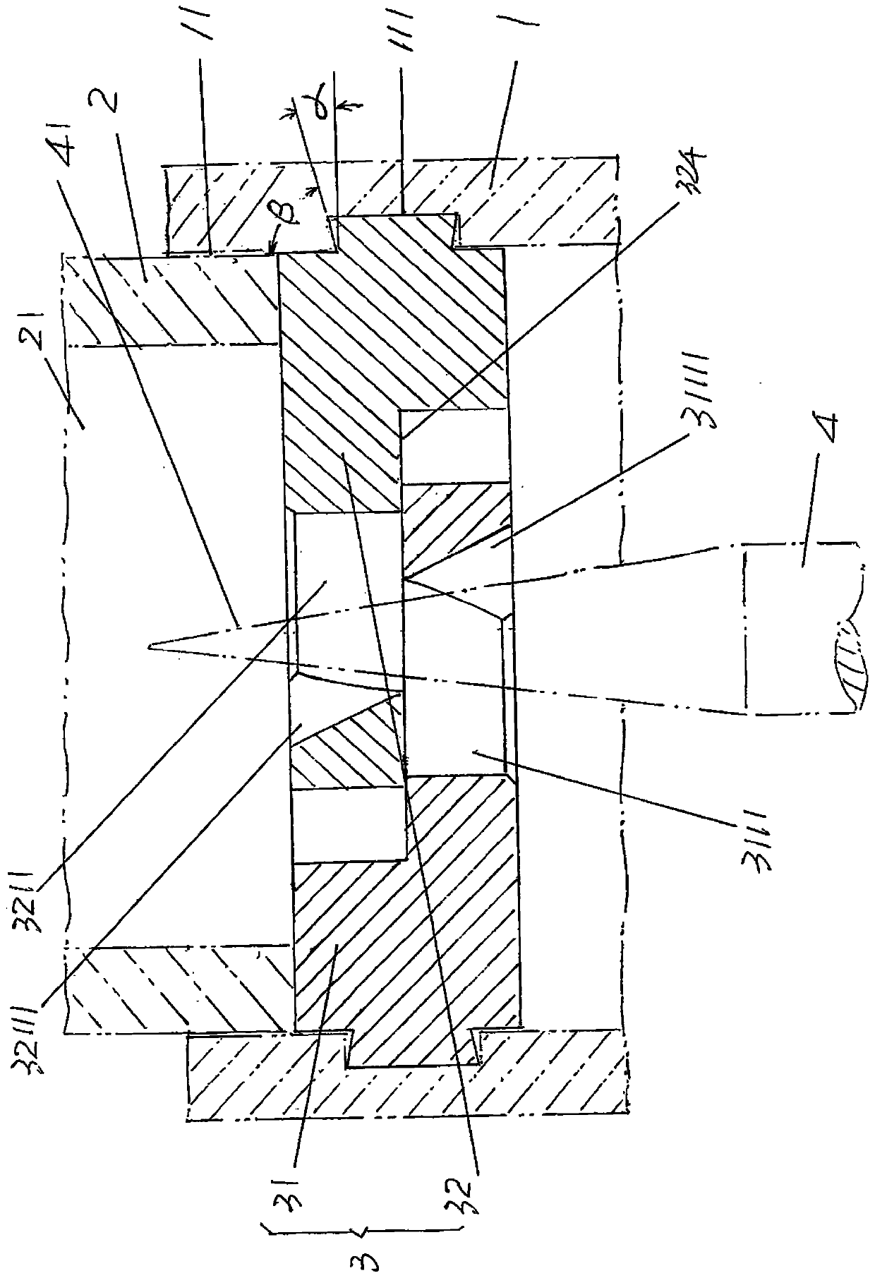
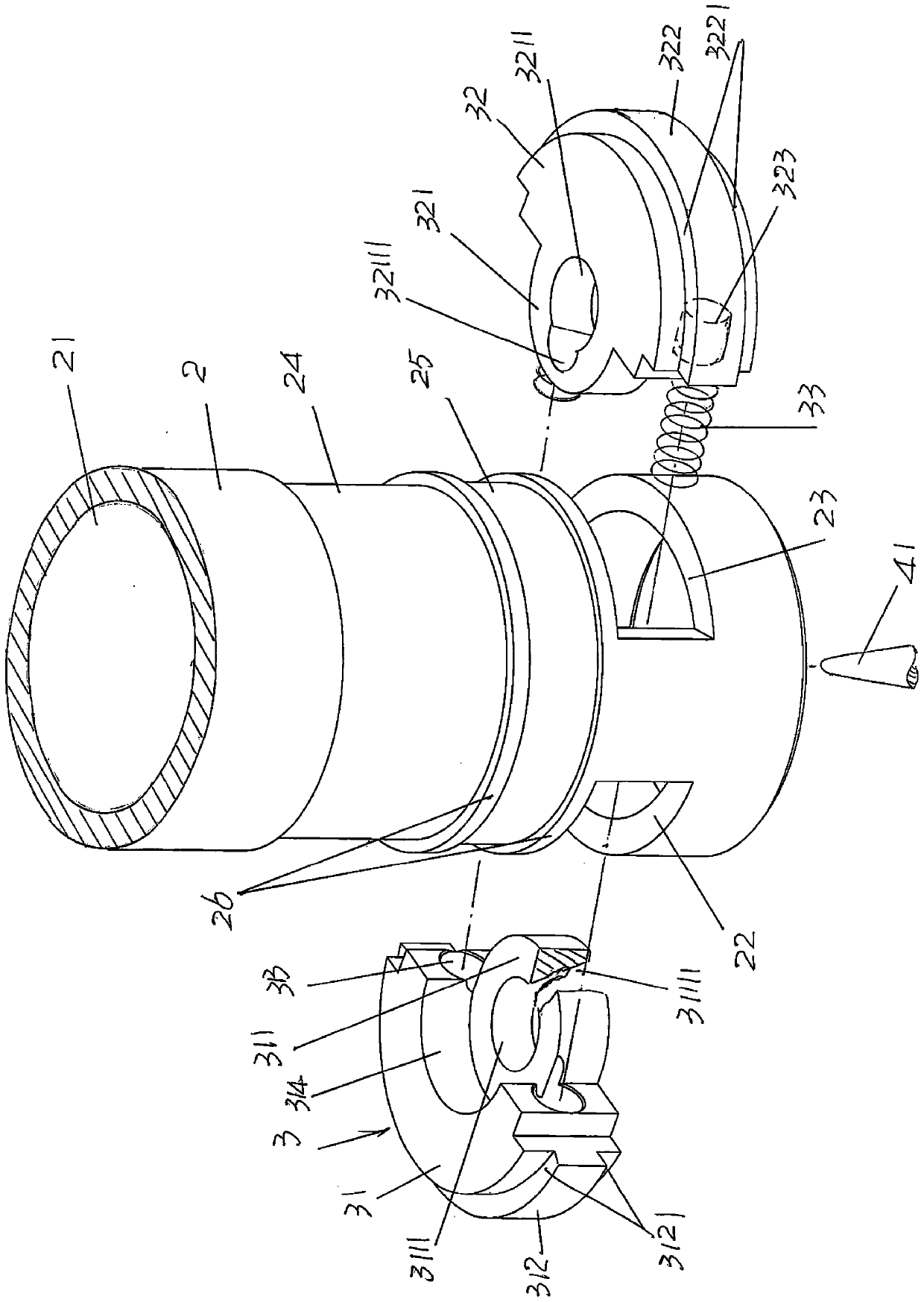
[0021] See figure 1 and figure 2, showing an outer tube body 1, a middle tube body 2 and a middle tube body drum butterfly 3, on the wall of the outer tube body cavity 11 at the end of the outer tube body 1 towards the middle tube body 2, that ...


PUM


Abstract

The invention discloses a matching structure for a drum plate and a pipe body locking groove of a telescopic baton, and belongs to the technical field of antiriot equipment for polices. The matching structure comprises an external pipe body, a middle pipe body and a middle pipe body drum plate, wherein a middle pipe body drum plate groove is formed in the cavity wall, facing one end of the middlepipe body, of the external pipe body; the middle pipe body is matched with the external pipe body; and the middle pipe body drum plate comprises a first plate, a second plate and a pair of plate piecesprings. The matching structure is characterized in that a first plate piece tooth platform is constituted on the side, facing the middle pipe body drum plate groove, of the first plate, and first plate piece tooth platform slopes are constituted on upper and lower surfaces of the first plate piece tooth platform; and a second plate piece tooth platform is constituted on the side, facing the middle pipe body drum plate groove, of the second plate, and inclination angles are formed between the first and second plate piece tooth platforms and upper and lower groove walls of the middle pipe bodydrum plate grooves. The matching structure can avoid the condition that the first and second plates of the middle pipe body drum plate slide out of the middle pipe body drum plate groove and moves tothe center of a middle pipe body cavity when receiving impact to cause the middle pipe body to retract into an external pipe body cavity.

Description

technical field [0001] The invention belongs to the technical field of anti-riot equipment for police use, and in particular relates to a matching structure of a drum butterfly and a pipe body locking groove of a retractable police baton. Background technique [0002] The aforementioned retractable baton is one of the police equipment worn by the public security police in our country, especially the public security police and armed police. Because it is a telescopic structure and is mostly used in the thrown state, it is also called "throwing stick" or " Neck Roller", etc. Usually, the number of sections of the telescopic baton is three sections, which are composed of outer tube body, middle tube body and rear tube body (also known as "front tube body, middle tube body and rear tube body"). For this, please refer to patents such as CN104457414A (Telescopic batons that can improve assembly convenience and stability), CN105865259A (positioning control mechanism for telescopic...

Claims


Application Information

Patent Timeline
Patent Type & Authority Applications(China)
IPC IPC(8): F41B15/02
CPCF41B15/02F41B15/027
Inventor 胡天明吴根如
Owner 常熟市吉宏精密机械有限公司
Why Eureka
Try Eureka