Satellite-borne deployable parabolic cylinder antenna

A parabolic cylinder and parabola technology, applied in the field of satellite antennas, can solve the problems of low surface accuracy, surface accuracy, poor stability, and poor reliability, and achieve the effects of reducing manufacturing difficulty, ensuring surface accuracy, and reducing difficulty

Active Publication Date: 2020-05-01
SHANGHAI SPACEFLIGHT INST OF TT&C & TELECOMM
View PDF7 Cites 5 Cited by
  • Summary
  • Abstract
  • Description
  • Claims
  • Application Information

AI Technical Summary

Problems solved by technology

The inflatable antenna realizes the deployment of the antenna by inflating air, but due to the inherent factors such as strong fluidity of the gas, the accuracy and stability of the shape and surface after deployment are poor
The fixed surface deployable antenna can be folded and unfolded through the relative rotation of the units. Each unit is composed of a rigid back frame supporting a solid reflective surface. After the deployment, the surface accuracy is high, but the weight of the rigid back frame and the solid surface is large, and it is difficult to meet the lightweight requirements.
The deployable mesh antenna realizes the deployment and support of the reflective surface through various deployable truss structures. It is light in weight, but the wire mesh reflective surface needs to be adjusted repeatedly after deployment, and the control is complicated and the surface accuracy is low.
At the same time, the structure of the expandable truss is complex and its reliability is poor. Once the expansion mechanism fails during the expansion process, inestimable losses will occur

Method used


Image

  • Satellite-borne deployable parabolic cylinder antenna
  • Satellite-borne deployable parabolic cylinder antenna
  • Satellite-borne deployable parabolic cylinder antenna

Examples


Embodiment Construction

[0032] A spaceborne deployable parabolic antenna proposed by the present invention will be described in further detail below in conjunction with the accompanying drawings and specific embodiments. Advantages and features of the present invention will be apparent from the following description and claims.

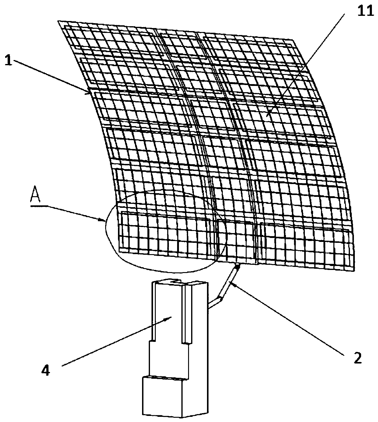
[0033] see Figure 1 to Figure 4 As shown, the present invention provides a space-borne deployable parabolic antenna, which includes a reflector module 1 , a deployable arm module 2 and a retractable wrapping belt 3 .

[0034] see figure 1 As shown, the reflective surface module 1 is composed of several fixed network reflective surface units 11 arranged in an array. In this embodiment, the reflective surface module 1 is composed of 3*N fixed network reflective surface units 11 arranged in an array. The surface module 1 is arranged with three fixed-net reflecting surface units 11 on the linear dimension, and the reflecting surface module 1 is arranged with N fixed-net refle...


PUM


Abstract

The invention discloses a satellite-borne deployable parabolic cylinder antenna. The antenna comprises a reflecting surface module, an unfolding arm module and a folding wrapping tape, wherein the reflecting surface module is formed by arranging a plurality of fixed network reflecting surface units in an array manner; the fixed network reflecting surface unit comprises a supporting frame and a metal wire network reflecting surface; one dimension of the supporting frame is a linear dimension; the other dimension is a parabola dimension; the metal wire network reflecting surface is laid in the middle of the supporting frame; the plurality of fixed network reflecting surface units arranged along the parabola dimension are sequentially and rotationally connected; when the parabolic cylinder antenna is in an unfolded state, the plurality of fixed network reflecting surface units arranged along the parabola dimension form a parabolic cylindrical surface; when the parabolic cylinder antenna is in a folded state, the plurality of fixed network reflecting surface units arranged along the parabola dimension is folded in a folding fan mode. The reflecting surface units adopt a fixed network combined frame type design, the advantages of a fixed-surface deployable antenna and a network-surface deployable antenna are integrated, and the lightweight requirement of the antenna is met on the basis of realizing a high-shape-surface-precision reflecting surface.

Description

technical field [0001] The invention belongs to the technical field of satellite antennas, in particular to a space-borne deployable parabolic cylinder antenna. Background technique [0002] Due to its high gain, strong directivity, and easy automatic beam scanning, parabolic antennas are widely used in radio astronomy, electronic reconnaissance and other space missions that require strong directivity antennas. With the continuous development of aerospace technology, the requirements of multi-function, multi-band, and high-power satellites have prompted the development of antennas in the direction of large apertures. However, limited by the carrying capacity of the launch vehicle, the large-diameter antenna must be made expandable, and it is constantly developing towards a large folding ratio and light weight. [0003] Currently, there are three types of deployable parabolic antennas that are widely used, namely, air-filled deployable antennas, fixed-surface deployable ante...

Claims


Application Information

Patent Timeline
Patent Type & Authority Applications(China)
IPC IPC(8): H01Q1/08H01Q1/12H01Q1/28H01Q15/14H01Q15/16
CPCH01Q1/288H01Q1/08H01Q1/1235H01Q15/14H01Q15/162
Inventor 张健军刘嘉琛张丽娜苏晟刘伟栋张瑞珏
Owner SHANGHAI SPACEFLIGHT INST OF TT&C & TELECOMM
Why Eureka
Try Eureka