
A flushing device capable of controlling the drainage of a water tank through the opening and closing of the toilet lid

A technology of opening and closing control and toilet lid, which is applied to flushing equipment with water tanks, water supply devices, buildings, etc., can solve the problems of high implementation cost, harm to human health, shortened service life, etc., and achieves low implementation cost and low transformation difficulty. , The effect of high working stability

Inactive Publication Date: 2021-01-05
黄志平
View PDF8 Cites 0 Cited by
  • Summary
  • Abstract
  • Description
  • Claims
  • Application Information

AI Technical Summary

Problems solved by technology

Among them, traditional toilet flushing devices mostly use manual pulling or pressing to realize flushing. The position of the toilet lid does not affect the flushing effect when flushing, and it is difficult to develop the habit of flushing after closing the toilet lid; now Most of the flushing systems with intelligent toilets use electronic components to control the water and use solenoid valves to realize flushing, and can automatically close the toilet lid and flush automatically
However, the implementation cost is high, and the service life of electronic components such as water solenoid valves is easily shortened after long-term contact with over-humid air, and there may be safety hazards such as electric leakage.
[0003] In most households, toileting, washing, and showering are all carried out in the bathroom. When the toilet is flushed directly without the lid, the instantaneous cyclone in the toilet is likely to form aerosols, emit peculiar smell, affect air quality, and then pollute toothbrushes and mouthwash. Cups, towels and other daily necessities, indirectly endangering human health

Method used


Image

  • A flushing device capable of controlling the drainage of a water tank through the opening and closing of the toilet lid

Examples


Embodiment Construction

[0024] The specific implementation manners of the present invention will be described in further detail below in conjunction with the accompanying drawings.

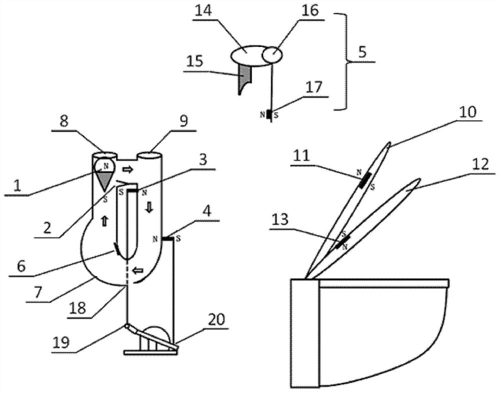
[0025] As shown in the attached figure, the flushing device mainly includes a hollow magnetic float (1), an irregular U-shaped ring pipe (7), a magnetic opening flushing module (3), a magnetic closing flushing module (4), and a manual drainage button (5), permanent magnet A (11) and permanent magnet B (13).

[0026] The upper part of the hollow magnetic float (1) is composed of a hollow sphere, and the lower part is a conical solid permanent magnet. The weight of the hollow magnetic float (1) is slightly smaller than the buoyancy of water on it, and the magnetic point of the solid permanent magnet is S pole. , the starting position of the hollow magnetic floating ball (1) is on the left side of the irregular U-shaped ring pipe (7), and the end farther away from the position of the toilet seat.

[0027] The slightly lowe...


PUM


Abstract

The invention relates to a flushing device capable of controlling drainage of a toilet water tank by opening and closing a toilet lid by utilizing the principles of magnetic force and buoyancy. The device mainly comprises a hollow magnetic floating ball (1), an irregular U-shaped ring pipe (7), a magnetic opening flushing module (3), a magnetic closing flushing module (4), a permanent magnet A (11), a permanent magnet B (13) and a manual drainage key (5). The hollow magnetic floating ball (1) is started to move clockwise along the irregular U-shaped annular pipe (7) through opening and closingof the toilet lid with the permanent magnet A (11), the magnetic opening flushing module (3) and the magnetic closing flushing module (4) are triggered in sequence, a water tank water sealing cover is controlled to be opened and closed, and the drainage effect is achieved. A toilet seat with the permanent magnet B (13) is lifted to repel magnetism to close the flushing module (4), the closing endof the water sealing cover is triggered to fail, and the effect of little drainage is achieved. In addition, the manual drainage key (5) is used for manually pressing drainage and serves as a necessary supplement of the toilet flushing device.

Description

technical field [0001] The invention relates to a flushing device for a toilet water tank, in particular to a flushing device which can control the drainage of the toilet water tank through the opening and closing of the toilet lid by using the principle of magnetic force and buoyancy. Background technique [0002] Flush toilet is generally used in numerous families and various public places. Among them, traditional toilet flushing devices mostly use manual pulling or pressing to realize flushing. The position of the toilet lid does not affect the flushing effect when flushing, and it is difficult to develop the habit of flushing after closing the toilet lid; now Most of the flushing systems with intelligent toilets use electronic components to control water and use solenoid valves to realize flushing, and can automatically flush after closing the toilet lid automatically. However, the implementation cost is high, and the service life of electronic components such as water ...

Claims


Application Information

Patent Timeline
Patent Type & Authority Patents(China)
IPC IPC(8): E03D5/04
CPCE03D5/04
Inventor 黄志平
Owner 黄志平
Learn More