Lubricating oil amount adjustment mechanism, compressor, refrigerator

A technology for adjusting structure and oil volume, applied in the field of compressor manufacturing, can solve the problems of excessive lubricating oil, affecting the performance of the system heat transfer efficiency, compressor performance, and high system oil discharge rate, so as to prevent the exhaust with large oil volume. Effect

Active Publication Date: 2021-10-29
ZHUHAI GREE REFRIGERATION TECH CENT OF ENERGY SAVING & ENVIRONMENTAL PROTECTION
View PDF10 Cites 0 Cited by
  • Summary
  • Abstract
  • Description
  • Claims
  • Application Information

AI Technical Summary

Problems solved by technology

[0002] As the speed of the piston compressor continues to increase, the amount of crankshaft oil thrown off continues to increase, and the lubricating oil thrown off by the crankshaft moves in a parabola and spreads throughout the compressor housing, especially the cylinder bore U of the cylinder block. The amount of lubricating oil at the U-shaped groove will accumulate more and more lubricating oil with the increase of the crankshaft speed. During the reciprocating movement of the piston, the lubricating oil accumulated at the U-shaped groove will enter the cylinder following the reciprocating movement of the piston. The increase in the amount of oil will lead to an increase in the amount of oil in the exhaust gas after compression and a higher oil discharge rate in the system, which will subsequently affect the heat transfer efficiency of the system and the performance of the compressor
The usual treatment method is to open a hole in the U-shaped groove, and the lubricating oil thrown out by the crankshaft flows through the U-shaped groove of the cylinder block, and then flows downward from the oil hole to reduce the oil accumulation at the U-shaped groove of the cylinder block. , can partially reduce the accumulation of the amount of lubricating oil entering the cylinder hole, but it still cannot prevent the lubricating oil from flowing through the piston from the U-shaped groove of the cylinder block, and cannot fundamentally solve the problem of excessive lubricating oil. Based on this, this paper proposes invention

Method used


Image

  • Lubricating oil amount adjustment mechanism, compressor, refrigerator
  • Lubricating oil amount adjustment mechanism, compressor, refrigerator
  • Lubricating oil amount adjustment mechanism, compressor, refrigerator

Examples


Embodiment Construction

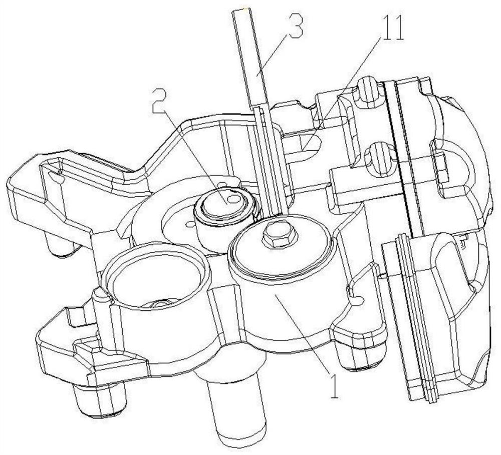
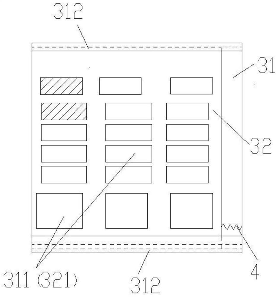
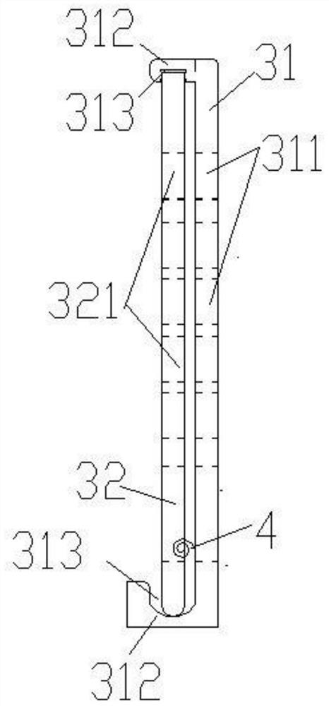
[0021] see in conjunction Figure 1 to Figure 4 As shown, according to an embodiment of the present invention, a lubricating oil amount adjustment structure is provided, including a cylinder block 1 and a crankshaft 2, the cylinder block 1 has a cylinder portion, the crankshaft 2 is rotatably connected to the cylinder block 1, and the A groove 11 is configured on the cylinder part. It can be understood that the groove 11 runs through the inside and outside of the cylinder part. The purpose of the groove 11 is to facilitate the assembly of the connecting rod in the compressor. The U-shaped groove can also be grooves of other shapes, and the present invention is not particularly limited. An oil volume adjustment assembly 3 is also provided between the groove 11 and the crankshaft 2, and the oil volume adjustment assembly 3 The amount of lubricating oil thrown into the groove 11 by the lubricating oil thrown off by the crankshaft 2 can be adjusted. In this technical solution, th...


PUM


Abstract

The invention provides a lubricating oil quantity regulating structure, a compressor and a refrigerator. One of the lubricating oil amount adjustment structures includes a cylinder block and a crankshaft, the cylinder block has a cylinder part, the crankshaft is connected to the cylinder block in rotation, a groove is formed on the cylinder part, and the groove is connected to the cylinder part. An oil quantity adjustment assembly is also arranged between the crankshafts, and the oil quantity adjustment assembly can adjust the amount of lubricating oil thrown from the crankshaft into the groove. The lubricating oil amount adjustment structure, compressor, and refrigerator provided by the present invention, by setting the lubricating oil flow adjustment assembly between the groove and the crankshaft, regulate and control the amount of lubricating oil thrown out from the crankshaft to the groove, effectively preventing Too much lubricating oil accumulated in the groove will lead to a large amount of oil in the exhaust of the compressor and a high oil discharge rate of the system.

Description

technical field [0001] The invention belongs to the technical field of compressor manufacturing, and in particular relates to a lubricating oil quantity regulating structure, a compressor and a refrigerator. Background technique [0002] As the speed of the piston compressor continues to increase, the amount of crankshaft oil thrown off continues to increase, and the lubricating oil thrown off by the crankshaft moves in a parabola and spreads throughout the compressor housing, especially the cylinder bore U of the cylinder block. The amount of lubricating oil at the U-shaped groove will accumulate more and more lubricating oil with the increase of the crankshaft speed. During the reciprocating movement of the piston, the lubricating oil accumulated at the U-shaped groove will enter the cylinder following the reciprocating movement of the piston. The increase in the amount of oil will lead to an increase in the amount of oil in the exhaust after compression and a higher oil d...

Claims


Application Information

Patent Timeline
Patent Type & Authority Patents(China)
IPC IPC(8): F04B39/02F04B39/00
CPCF04B39/0094F04B39/0207
Inventor 张率华熊克强申婷严耀宗
Owner ZHUHAI GREE REFRIGERATION TECH CENT OF ENERGY SAVING & ENVIRONMENTAL PROTECTION
Why Eureka
Try Eureka