Device for conveniently replacing illuminating lamp based on wind-driven motor

A technology of wind motors and lighting lamps, which is applied to lighting devices, lighting auxiliary devices, lighting device components, etc. It can solve the problems of personal threats to maintenance personnel, difficulty in replacement, and low efficiency, so as to avoid difficulty in replacement and reduce use costs. , the effect of ensuring safety

Active Publication Date: 2020-05-05
NINGBO EHOME ELECTRONICS
View PDF4 Cites 1 Cited by
  • Summary
  • Abstract
  • Description
  • Claims
  • Application Information

AI Technical Summary

Problems solved by technology

[0002] Lighting lamps have provided sufficient and good lighting and detection for people at night for a long time. However, since lighting lamps are generally supported by light poles with a relatively high height, lighting fixtures are generally set at the top of this type of light pole or near the top. The location of the lamps is generally high. When the lighting lamps fail due to long-term use, they need to be replaced in time to avoid affecting the lighting work. The traditional replacement method is generally replaced by manual work, and high-altitude operations also cause certain damage to the maintenance personnel. Threat, and in some places where electric repair vehicles are difficult to enter, it causes difficulty in replacement and high cost, and the efficiency is low

Method used


Image

  • Device for conveniently replacing illuminating lamp based on wind-driven motor
  • Device for conveniently replacing illuminating lamp based on wind-driven motor
  • Device for conveniently replacing illuminating lamp based on wind-driven motor

Examples


Embodiment Construction

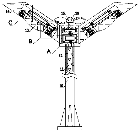
[0021] Combine below Figure 1-8 The present invention is described in detail, and for convenience of description, the orientations mentioned below are now stipulated as follows: figure 1 The up, down, left, right, front and back directions of the projection relationship itself are the same.

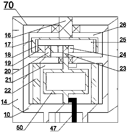
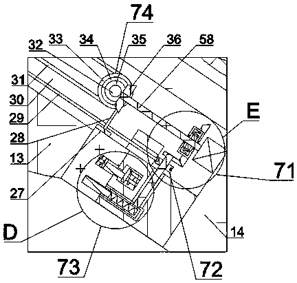
[0022] refer to Figure 1-8 According to an embodiment of the present invention, a device for convenient replacement of lighting lamps based on wind power motors includes a rod body 10, a lampshade 14 is fixed symmetrically on the upper end of the rod body 10, and an electromagnetic cavity 21 is arranged inside the rod body 10. The cavity 21 is provided with a wind power generating mechanism 70, and the lampshade 14 is provided with a power cavity 30 with its opening facing downward. The drive mechanism 71 is provided in the power cavity 30, and a driven mechanism 72 is provided on the lower side of the drive mechanism 71. , the lower side of the driven mechanism 72 is connected with a...


PUM


Abstract

The invention discloses a device for conveniently replacing an illuminating lamp based on a wind-driven motor, which comprise a rod body, lampshades are fixed to the upper end of the rod body in a bilateral symmetry mode, an electromagnetic cavity is formed in the rod body; a wind power generation mechanism is arranged in the electromagnetic cavity; a power cavity with a downward opening is formedin the lampshade, a driving mechanism is arranged in the power cavity; a driven mechanism is arranged on the lower side of the driving mechanism; the lower side of the driven mechanism is connected with a locking mechanism; the driving mechanism is connected with a transmission mechanism; wind power can be converted into electric power to be stored through the wind-driven motor; an emergency standby power supply during power failure can be provided; and when the illuminating lamp breaks down, the lifting illuminating lamp can be maintained and replaced through external control, so that the replacement difficulty caused by faults is avoided, the replacement safety of maintenance personnel is guaranteed, the replacement efficiency is improved, and the use cost during replacement is reduced.

Description

technical field [0001] The invention relates to the technical field of motors, in particular to a device for conveniently replacing lighting lamps based on wind-powered motors. Background technique [0002] Lighting lamps have provided sufficient and good lighting and detection for people at night for a long time. However, since lighting lamps are generally supported by light poles with a relatively high height, lighting fixtures are generally set at the top of this type of light pole or near the top. The location of the lamps is generally high. When the lighting lamps fail due to long-term use, they need to be replaced in time to avoid affecting the lighting work. The traditional replacement method is generally replaced by manual work, and high-altitude operations also cause certain damage to the maintenance personnel. Threat, and in some positions where electric repair vehicles are difficult to enter, it causes difficulty in replacement, high cost, and low efficiency. Co...

Claims


Application Information

Patent Timeline
Patent Type & Authority Applications(China)
IPC IPC(8): F21S9/02F21S9/04F21V23/00F21V21/38
CPCF21S9/026F21S9/043F21V21/38F21V23/003
Inventor 不公告发明人
Owner NINGBO EHOME ELECTRONICS
Why Eureka
Try Eureka