
Airbag for vehicle occupant restraint system

An airbag and occupant restraint technology, applied in vehicle safety arrangements, pedestrian/passenger safety arrangements, vehicle components, etc.

Pending Publication Date: 2020-05-08
TRW AUTOMOTIVE SAFETY SYSTEMS GMBH & CO KG +2
View PDF9 Cites 0 Cited by
  • Summary
  • Abstract
  • Description
  • Claims
  • Application Information

AI Technical Summary

Problems solved by technology

However, there are situations where reclosing of the vent hole is undesirable and a continuously open vent hole would facilitate occupant restraint

Method used


Image

  • Airbag for vehicle occupant restraint system
  • Airbag for vehicle occupant restraint system
  • Airbag for vehicle occupant restraint system

Examples


Embodiment Construction

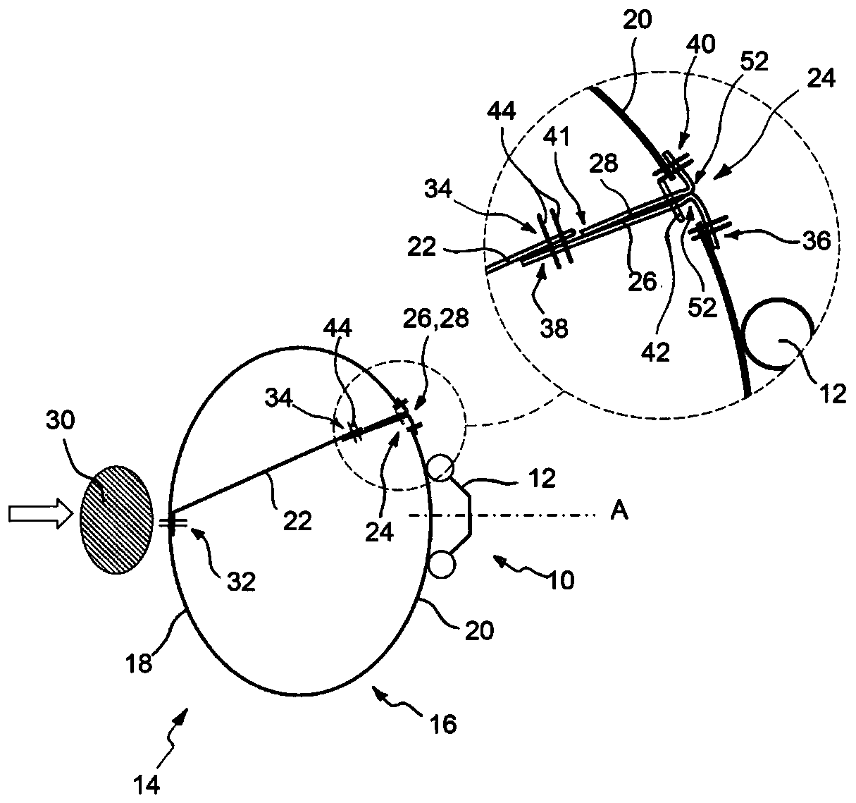
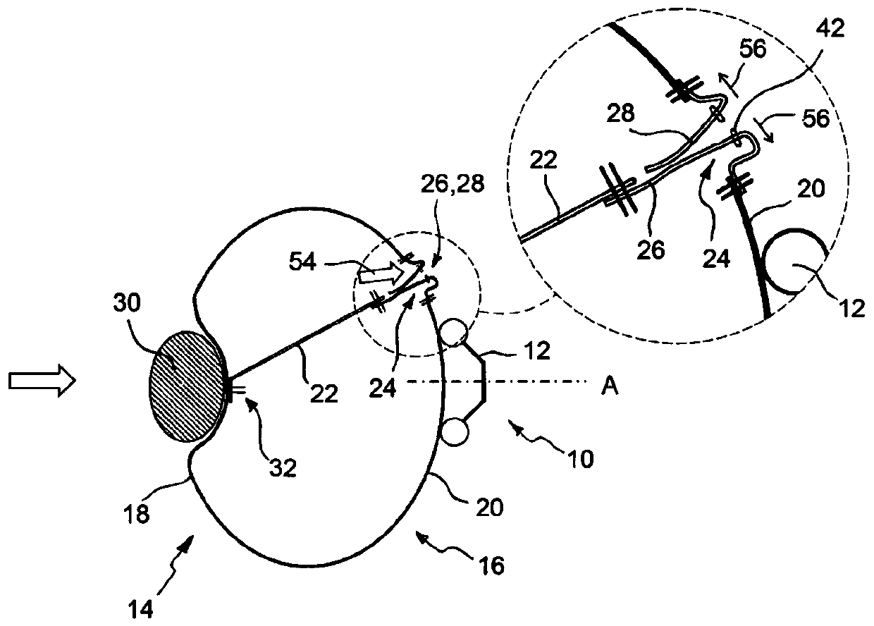
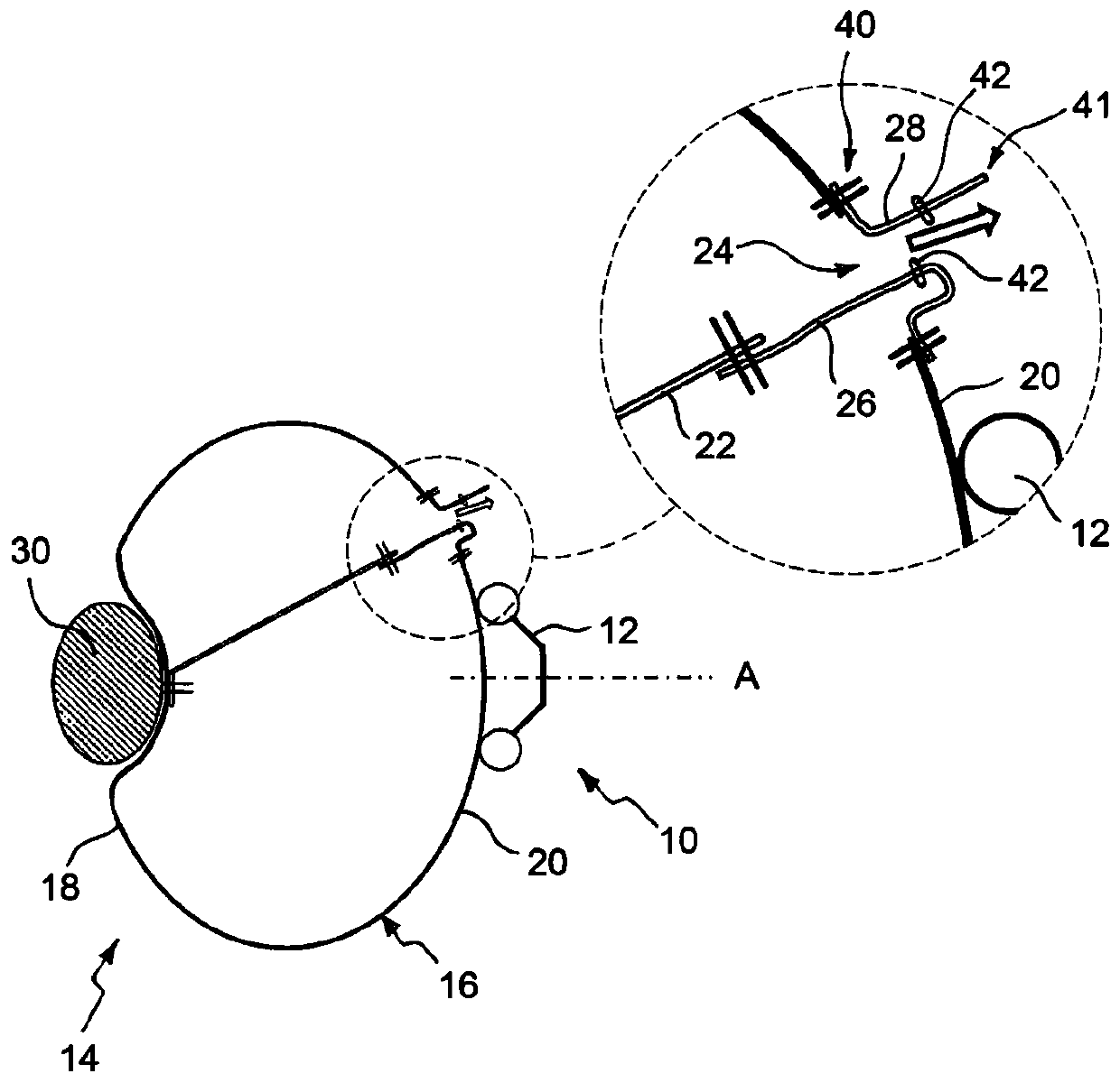
[0022] Figures 1 to 4 A steering wheel assembly 10 is shown comprising a vehicle steering wheel 12 rotatable about a steering axis A and an airbag module mounted in the region of the steering wheel hub and comprising an airbag 14 for a vehicle occupant restraint system.

[0023] The airbag 14 includes an airbag panel 16 defining an inflatable airbag volume and including a front panel portion 18 and a rear panel portion 20, a tether 22 extending inside the airbag 14 across the inflatable airbag volume, a tether formed in the airbag A discharge aperture 24 in the rear panel portion 20 of the panel 16 and a first closure tab 26 and a second closure tab 28 for closing the discharge aperture 24 . In this regard, the portion of the airbag panel 16 that faces the vehicle occupant 30 in the inflated state of the airbag 14 is referred to as the front panel portion 18, wherein in Figures 1 to 4 The head of the vehicle occupant 30 is only schematically shown in FIG. Accordingly, the ...


PUM


Abstract

An airbag for a vehicle occupant restraint system includes an airbag panel defining an inflatable airbag volume and including a front panel portion and a rear panel portion; a tether extending acrossthe inflatable airbag volume inside the airbag; a discharge hole formed in a rear panel portion of the airbag panel; and a first closing tab and a second closing tab for closing the discharge hole, the tether extends from a first tether end tightly connected to the front panel part to an opposite second tether end along the direction of the discharge hole; a first closure tab extends from a firsttab end closely connected to the rear panel portion to a second tab end closely connected to a second tether end, the second closure tab being secured to the rear panel portion adjacent to the vent hole, the two closure tabs being coupled by a releasable connection when a vehicle occupant impacts the inflated airbag.

Description

technical field [0001] The present invention relates to an airbag for a vehicle occupant restraint system comprising: an airbag panel defining an inflatable airbag volume and having a front panel portion and a rear panel portion; a tether inside the airbag extending through the inflatable airbag volume; a vent hole formed in a rear panel portion of the airbag panel; and a first closure tab and a second closure tab for closing the vent hole, wherein the The tether extends from a first tether end tightly connected to the front panel portion to an opposite second tether end in the direction of the discharge hole, wherein the first closure tab is tightly connected to the rear panel The first tab end of the section extends to a second tab end closely connected to the second tether end, and the second closure tab is secured to the rear panel section adjacent the discharge aperture. Background technique [0002] It is known from the prior art that, in addition to a permanently ope...

Claims


Application Information

Patent Timeline
Patent Type & Authority Applications(China)
IPC IPC(8): B60R21/2338B60R21/239
CPCB60R21/2338B60R21/239B60R2021/2395B60R21/2342B60R2021/23382B60R21/203B60R2021/23384
Inventor 托马斯·林德斯蒂芬·萨蓬齐斯拉蒙·巴纳·卡斯特罗巴尔托洛梅乌·弗朗哥亚历山德拉·巴尔巴斯·卡尔沃迪奥戈·冈卡尔维斯·罗查
Owner TRW AUTOMOTIVE SAFETY SYSTEMS GMBH & CO KG
Learn More