Device for transporting objects

An article, ball roller technology, applied in the direction of linear motion bearings, manufacturing tools, mechanical equipment, etc., can solve the problems of inconspicuous marking, error-prone marking system, correctly meeting the marking and therefore difficult to correct position, etc. achieve the effect of easy orientation

Active Publication Date: 2017-08-01
HARTING ELECTRIC GMBH & CO KG
View PDF10 Cites 1 Cited by
  • Summary
  • Abstract
  • Description
  • Claims
  • Application Information

AI Technical Summary

Problems solved by technology

In the case of several different workpieces, which are processed on the same machine, the marking becomes very inconspicuous and the marking system very error-prone
Furthermore, with heavy workpieces it is difficult to correctly meet the marks and thus the correct position

Method used


Image

  • Device for transporting objects
  • Device for transporting objects
  • Device for transporting objects

Examples


Embodiment Construction

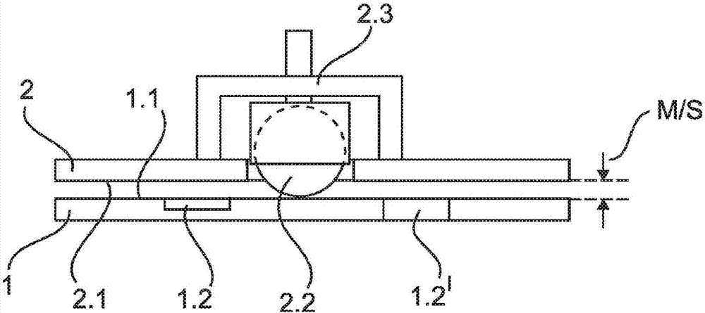
[0042] figure 1 A schematic diagram of a device according to the invention is shown. The device consists of a first structure 1 and a second structure 2 . The two structures 1 , 2 are each configured as a metal plate and are arranged parallel to one another. Here, the first structure 1 is arranged below the second structure 2 and serves as a base for the device. The second structure 2 is arranged above the first structure 1 . However, the device can also be used rotated by 180°, so that the first structure 1 is arranged above the second structure 2 .

[0043] The top of the first structure 1 is configured as a working surface 1.1 ( supporting surface) and facing the second structure 2. The underside of the second structure 2 is formed as a contact surface 2 . 1 and faces the first structure 1 . The working surface 1.1 and the contact surface 2.1 are oriented parallel and form a gap S here.

[0044] The gap S between the running surface 1.1 and the contact surface 2.1 is ...


PUM


Abstract

The invention relates to a device for transporting objects inside a machine. The device consists of a first structure (1) and a second structure (2) which are moveably arranged relative to one another. The second structure (2) has casters (2.2) which allow the structure to be moved easily. Openings (1.2) are provided in the first structure (1), into which openings the casters (2.2) can be inserted. When the casters (2.2) are inserted into the openings (1.2), the first structure (1) and the second structure (2) make contact, thereby preventing further movement. Multiple openings (1.2) allow the definition of different positions of the first structure (1) relative to the second structure (2).

Description

technical field [0001] The invention relates to a device for transporting objects. Such transport devices are required in order to be able to move objects to be processed in the production process, such as workpieces, printed circuit boards or other semi-finished products, to the processing machine. Depending on the machining step, the workpiece must be moved into the machine in order to be able to carry out different machining processes at different workstations on the workpiece. Background technique [0002] The processing machine can here be a drilling machine, a milling machine, a welding machine, a press, a stamping machine or another processing machine. If the processing machine does not have extensive possibilities for adjustment, the workpieces may have to be moved, aligned and fixed multiple times for different processing steps. [0003] The workpiece to be processed can have a high weight, which makes it difficult to move the workpiece onto the machine. Just in ...

Claims


Application Information

Patent Timeline
Patent Type & Authority Applications(China)
IPC IPC(8): B23Q1/58B23Q16/04
CPCB23Q1/58B23Q16/04F16C29/046F16C2326/00
Inventor K·沃姆克尔
Owner HARTING ELECTRIC GMBH & CO KG
Why Eureka
Try Eureka