Magnetic push suspension bearing unit

A suspension bearing and magnetic repulsion technology, applied in the direction of bearing components, bearings, shafts and bearings, can solve problems such as short service life, poor impact resistance, and fire

Inactive Publication Date: 2014-05-14
BEIJING LIANGMING TONGCHUANG WATER TREATMENT EQUIP DEV CENT
View PDF11 Cites 8 Cited by
  • Summary
  • Abstract
  • Description
  • Claims
  • Application Information

AI Technical Summary

Problems solved by technology

[0002] At present, most of the bearings used in the machinery industry are composed of bearing inner rings, outer rings and rolling elements in between, which generate friction during transmission and wear between transmission parts. In order to reduce wear, it is necessary to cool down and Lubrication, this kind of bearing has the disadvantages of low transmission efficiency, large wear and short service life, and the service life is short at high speed, which can only guarantee the normal working cycle of tens of hours
[0003] And the existing Chinese patent: 200520020138.4 discloses a permanent magnet magnetic levitation shaft, which is composed of inner and outer cylindrical magnets and two pairs of magnetic rings, so that the inner ring assembly is in a suspended state, but because its three acting force surfaces are installed in a closed In the housing, the structure requires high assembly technology and is not easy to install and debug; moreover, because the magnetic suspension bearing is a kind of flexible support, the impact resistance is poor, and external factors can easily cause radial and axial displacement of the shaft during rotation. Displacement or swing, and in the above patent, there is no limit protection mechanism in the axial and radial directions, and the displacement and swing of the rotating shaft will easily cause friction, fire or even explosion between the magnetic blocks, especially in the application of high-speed rotating shafts. In addition, most of the electromagnetic suspension bearings that can be seen on the market require high control precision, more complex structures, and very high cost, making them difficult to popularize and apply.

Method used


Image

  • Magnetic push suspension bearing unit
  • Magnetic push suspension bearing unit
  • Magnetic push suspension bearing unit

Examples


Embodiment 1

[0021] Embodiment 1 Axially suspended magnetic repulsion suspension bearing unit

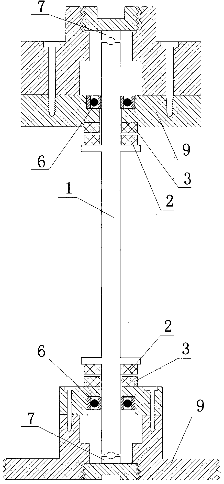
[0022] see figure 1 , the magnetic repulsion suspension bearing unit mainly includes: shaft, inner magnetic ring, outer magnetic ring, auxiliary bearing, limit block and bracket; the inner magnetic ring is installed at the proximal end of the shaft, and the outer magnetic ring corresponding to the inner magnetic ring is installed On the bracket, the adjacent surfaces of the inner magnetic ring and the outer magnetic ring are of the same polarity, and the inner magnetic ring and the outer magnetic ring form an axial magnetic ring pair; the limit block corresponding to the shaft end is installed on the support, and the limit block The gap with the end of the shaft is smaller than the gap between the inner magnetic ring and the outer magnetic ring; an auxiliary bearing is arranged between the shaft and the bracket. Auxiliary bearings are ceramic bearings. The pair of axial magnetic rings can also...

Embodiment 2

[0024] Embodiment 2 Axial and radial levitation magnetic repulsion levitation bearing unit

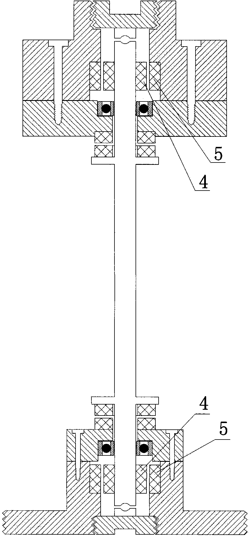
[0025] see figure 2 and 5 , on the basis of Embodiment 1, in addition, it also includes an inner magnetic cylinder and an outer magnetic cylinder, the inner magnetic cylinder is concentric with the shaft and fixedly installed at the proximal end of the shaft, and the outer magnetic cylinder is sleeved outside the inner magnetic cylinder and fixedly installed on the bracket Above, the inner diameter of the outer magnetic cylinder is slightly larger than the outer diameter of the inner magnetic cylinder. Both the inner magnetic cylinder and the outer magnetic cylinder are radially magnetized. The adjacent surfaces of the inner magnetic cylinder and the outer magnetic cylinder are of the same polarity. The inner magnetic cylinder and the outer magnetic cylinder are composed of Radial magnetic cylinder pair; the gap between the auxiliary bearing and the bracket or between the auxiliary b...

Embodiment 3

[0027] Embodiment 3 Adding a magnetic repulsion suspension bearing unit with limit ball axial suspension

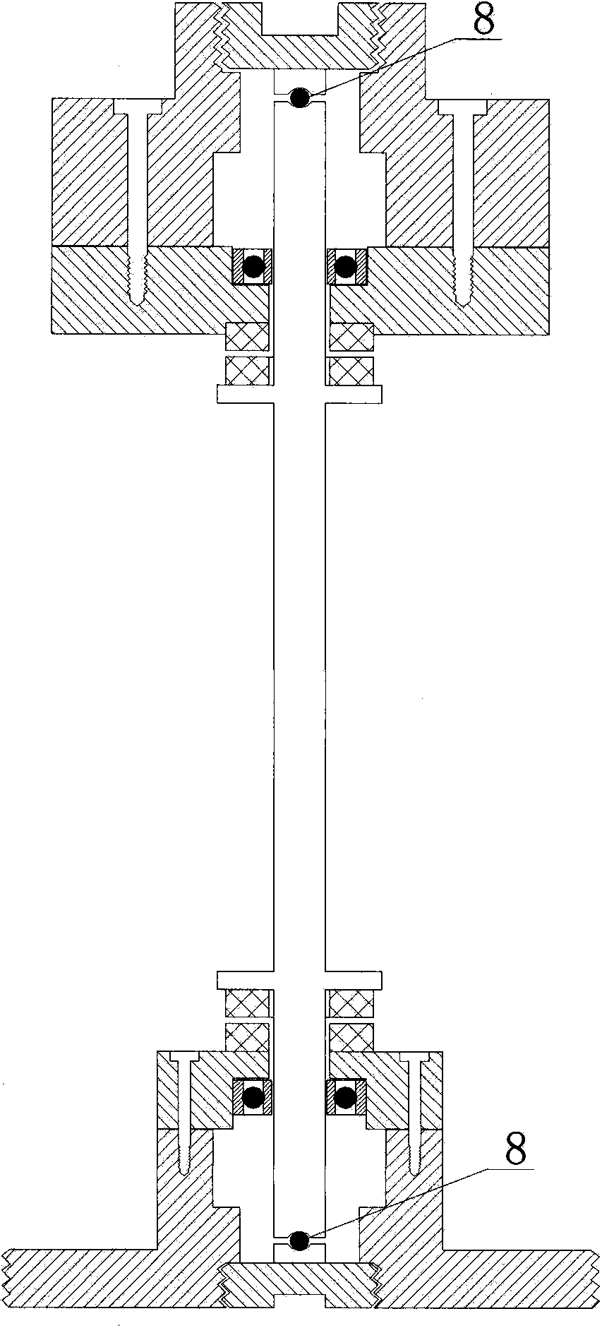
[0028] see image 3 , On the basis of Embodiment 1, further, limit balls are installed between the limit block and the shaft end. The limit block can be a ceramic block, and the limit ball can be a ceramic ball.

[0029] The advantage of this embodiment is: this embodiment not only has the advantages of Embodiment 1, but when the shaft moves axially, the sliding friction between the limit block and the end of the shaft is converted into rolling friction. The use of ceramics improves the service life.


PUM


Abstract

The invention discloses a magnetic push suspension bearing unit, comprising a shaft, an inner magnetic ring, an outer magnetic ring, an auxiliary bearing, a limiting block and a bracket, wherein the inner magnetic ring is arranged at the near end part of the shaft; the corresponding outer magnetic ring is arranged on the bracket; the adjacent surfaces of the two magnetic rings are the same in polarity; an inner magnetic barrel for magnetizing in a radial manner is arranged on the shaft; the inner magnetic barrel is sleeved with an outer magnetic barrel for magnetizing in the radial manner, and the outer magnetic barrel is fixedly arranged on the bracket; the adjacent surfaces of the two magnetic barrels are the same in polarity; the auxiliary bearing is also arranged between the shaft and the bracket; corresponding limiting block and limiting ball are arranged at the end of the shaft; a direct contact rolling body is not formed between the shaft and the bracket; the shaft and the bracket form a suspension state by virtue of a magnetic push shaft; the shaft and the bracket are free of friction, free of abrasion, high in transmission efficiency, free of cooling and lubricating, and long in service life, and the magnetic push suspension bearing unit has high applicable value in high-speed fields of aerospace and the like.

Description

technical field [0001] The invention relates to a rotating device, in particular to a bearing unit, in particular to a magnetic suspension bearing unit. Background technique [0002] At present, most of the bearings used in the machinery industry are composed of bearing inner rings, outer rings and rolling elements in between, which generate friction during transmission and wear between transmission parts. In order to reduce wear, it is necessary to cool down and Lubrication, this kind of bearing has the disadvantages of low transmission efficiency, large wear and short service life, and the service life is short at high speed, which can only guarantee the normal working cycle of tens of hours. [0003] And the existing Chinese patent: 200520020138.4 discloses a permanent magnet magnetic levitation shaft, which is composed of inner and outer cylindrical magnets and two pairs of magnetic rings, so that the inner ring assembly is in a suspended state, but because its three act...

Claims


Application Information

Patent Timeline
Patent Type & Authority Applications(China)
IPC IPC(8): F16C32/04
CPCF16C39/066
Inventor 佟宪良
Owner BEIJING LIANGMING TONGCHUANG WATER TREATMENT EQUIP DEV CENT
Why Eureka
Try Eureka