Supercharge Your Innovation With Domain-Expert AI Agents!

Height-adjustable supporting frame device

An adjustable, support frame technology, applied in the direction of machine/support, support machine, gun fixation, etc., can solve the problem of up and down swing, the two-way lock parts cannot perform synchronous unlocking action, the pressure is inconsistent, etc., to achieve synchronization Unlock the effect of the action

Pending Publication Date: 2020-05-08
慈溪市东鑫镁业有限公司
View PDF3 Cites 0 Cited by
  • Summary
  • Abstract
  • Description
  • Claims
  • Application Information

AI Technical Summary

Problems solved by technology

In the above-mentioned patent, the bottom of the first aluminum rod is directly connected to the center of the transmission block, and when the transmission block moves down, it is easy for each pressing arm of the transmission block to swing up and down around the center position, that is, each pressing arm of the transmission block One of the arms will be low and the other high. In this case, it will cause the pressure of each pressing arm of the transmission block to act on the second aluminum rod of each support rod to be inconsistent, so that the two-way movement of each support rod Locker parts cannot perform synchronous unlocking action, and even individual support rods cannot be effectively unlocked

Method used


Image

  • Height-adjustable supporting frame device
  • Height-adjustable supporting frame device
  • Height-adjustable supporting frame device

Examples


Embodiment 1

[0048] This embodiment shows the structure of a support frame device with two support rods 31 or a plurality of support rods 31 .

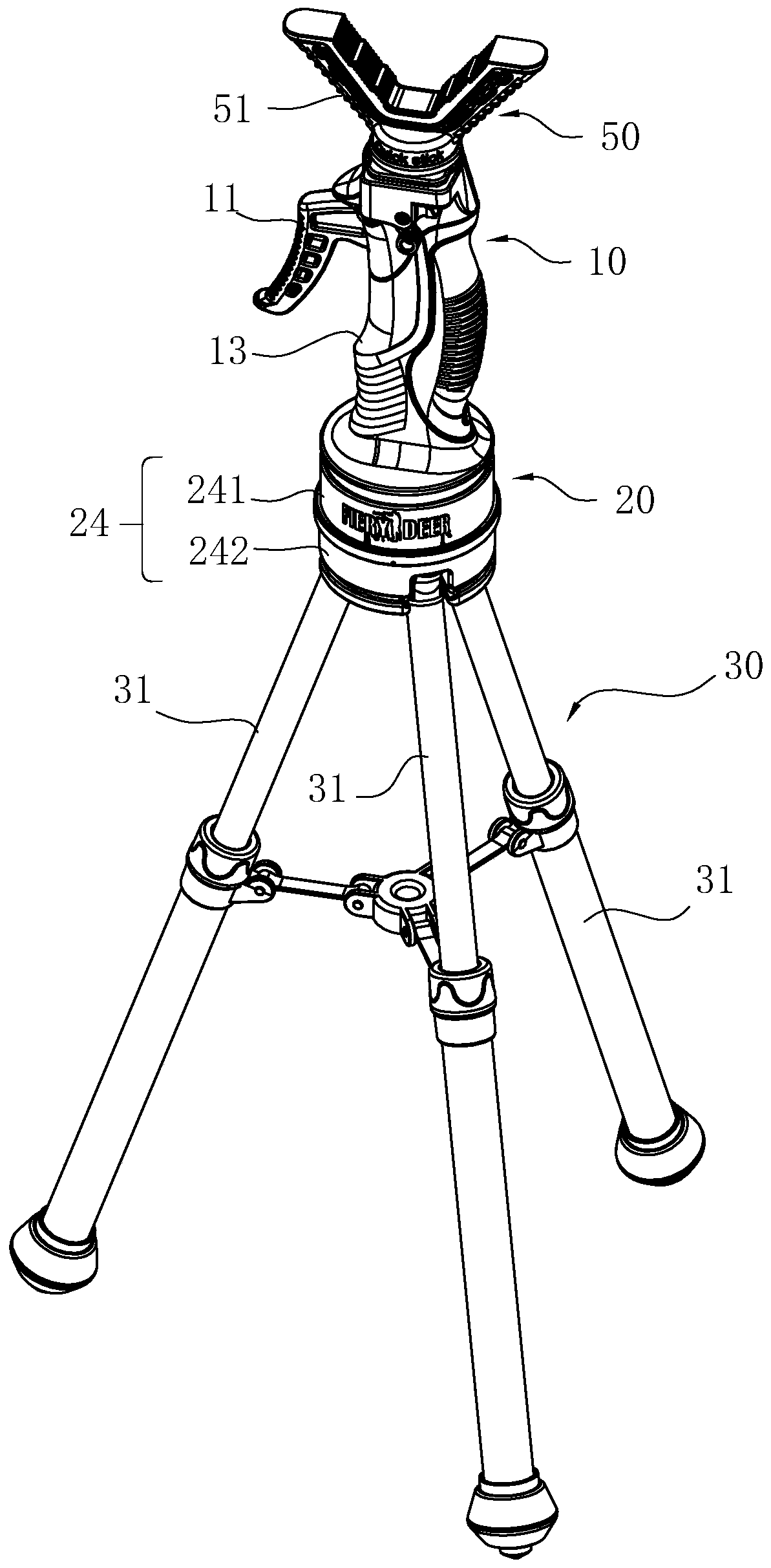
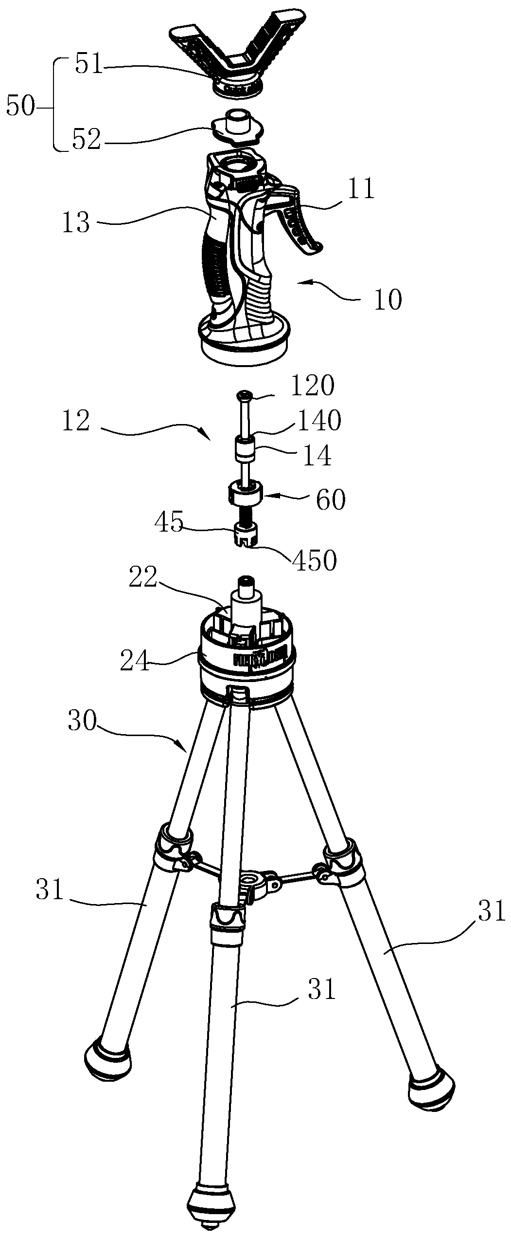
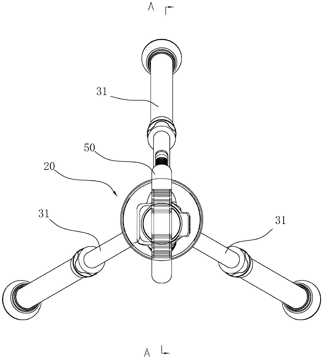
[0049] see Figure 1-Figure 17 , a height-adjustable support frame device includes a support head assembly 50 , a handle assembly 10 , a support seat assembly 20 , a support rod assembly 20 and a transmission mechanism 40 . The support head assembly 50 , the handle assembly 10 , the support seat assembly 20 and the support rod assembly 20 are arranged sequentially from top to bottom. The transmission mechanism 40 is disposed in the support seat assembly 20 .

[0050] see figure 2 , the support head assembly 50 includes a support head 51 and a connecting shaft 52 connected to the bottom of the support head 51 . The support head is detachably connected to the handle fixing seat 13 of the handle assembly 10 through the connecting shaft 52 at the bottom. The support head in this embodiment can be a V-shaped bracket for placing firearms and other ...

Embodiment 2

[0078] This embodiment shows the structure of a support frame device with a support rod 31 .

[0079] combine Figure 18 and Figure 19 , the support frame device in this embodiment has the same structure as the support frame device in Embodiment 1, and the support frame device in this embodiment also includes a support head assembly 50, a handle assembly 10, a support seat assembly 20, a support rod assembly 20 and a transmission mechanism 40 . Wherein, the support head assembly 50, the handle assembly 10 and the transmission mechanism 40 are all the same, the difference between this embodiment and the first embodiment is only that the support rod assembly 20 has one support rod 31, and the support rod 31 is vertically arranged. And the top of the support rod 31 is offset against the middle position of the bottom of the transmission block 23 , and the arc-shaped sheet 43 at the bottom of the transmission block 23 can be omitted in this embodiment. Of course, it is conceiva...


PUM


Abstract

The invention relates to a height-adjustable supporting frame device. The device comprises a handle assembly, a supporting seat assembly and a transmission mechanism, wherein the handle assembly comprises a handle and a driving rod linked with the handle and capable of moving up and down; the supporting seat assembly comprises a supporting seat with a movable cavity and a transmission block whichis arranged in the movable cavity of the supporting seat in an up-down movable mode, the transmission block is connected with the driving rod so that the transmission block can be driven by the driving rod to move, and the transmission block is further provided with an outer end part extending outwards from the middle; and the transmission mechanism is arranged in the movable cavity of the supporting seat and is provided with at least two power output ends and a power input end connected with the driving rod, and the power output ends synchronously act on the outer end part of the transmissionblock to drive the transmission block to move downwards. Due to the fact that the stress points of the transmission block are distributed at the outer end part, the transmission block can stably movedownwards, and the problem of shaking or inclining cannot occur, so that the pressure exerted on the top ends of supporting rods by the transmission block is consistent, and the synchronous unlockingaction of the supporting rods can be achieved.

Description

technical field [0001] The invention relates to the field of support frame equipment, in particular to a height-adjustable support frame device. Background technique [0002] Shooting, photography, monitoring equipment and other equipment often require support devices to provide auxiliary support so as to work better. [0003] For example, the Chinese utility model patent whose application number is CN201620036517.0 (authorized announcement number is: CN205278708U) discloses a "supporting device for shooting, photography, and monitoring equipment", which includes supporting heads connected sequentially from top to bottom Body assembly, handle assembly, holder assembly and support rod assembly. The handle assembly includes a trigger, the bottom end of the trigger is fixed with a first aluminum rod, a spring can be sleeved on the first aluminum rod, and the first aluminum rod can pass through the bottom of the handle body and be located in the slot of the fixing part. The su...

Claims


Application Information

Patent Timeline
IPC IPC(8): F16M11/04F16M11/18F16M11/26F16M11/34F41A23/10F41A23/14
CPCF16M11/046F16M11/18F16M11/26F16M11/34F41A23/10F41A23/14
Inventor 陈建丰
Owner 慈溪市东鑫镁业有限公司
Features
  • R&D
  • Intellectual Property
  • Life Sciences
  • Materials
  • Tech Scout
  • Unparalleled Data Quality
  • Higher Quality Content
  • 60% Fewer Hallucinations
Learn More