Method for manufacturing profiles by winding variable-section strips

A strip and cross-section technology, applied in the field of producing molding components, can solve the problem of unsuitable molding components, etc., and achieve the effect of high stability

Active Publication Date: 2022-07-05
MICHELIN & CO CIE GEN DES ESTAB MICHELIN
View PDF6 Cites 0 Cited by
  • Summary
  • Abstract
  • Description
  • Claims
  • Application Information

AI Technical Summary

Problems solved by technology

[0010] However, the methods described in the aforementioned documents have not proven suitable for producing shaped element parts with a relatively narrow base of triangular cross-section, e.g. figure 1 The profiled element parts P3, P5, P7, P9, P11, P13 shown in and form the substantially triangular cross-section of the reinforcing element

Method used


Image

  • Method for manufacturing profiles by winding variable-section strips
  • Method for manufacturing profiles by winding variable-section strips
  • Method for manufacturing profiles by winding variable-section strips

Examples


Embodiment Construction

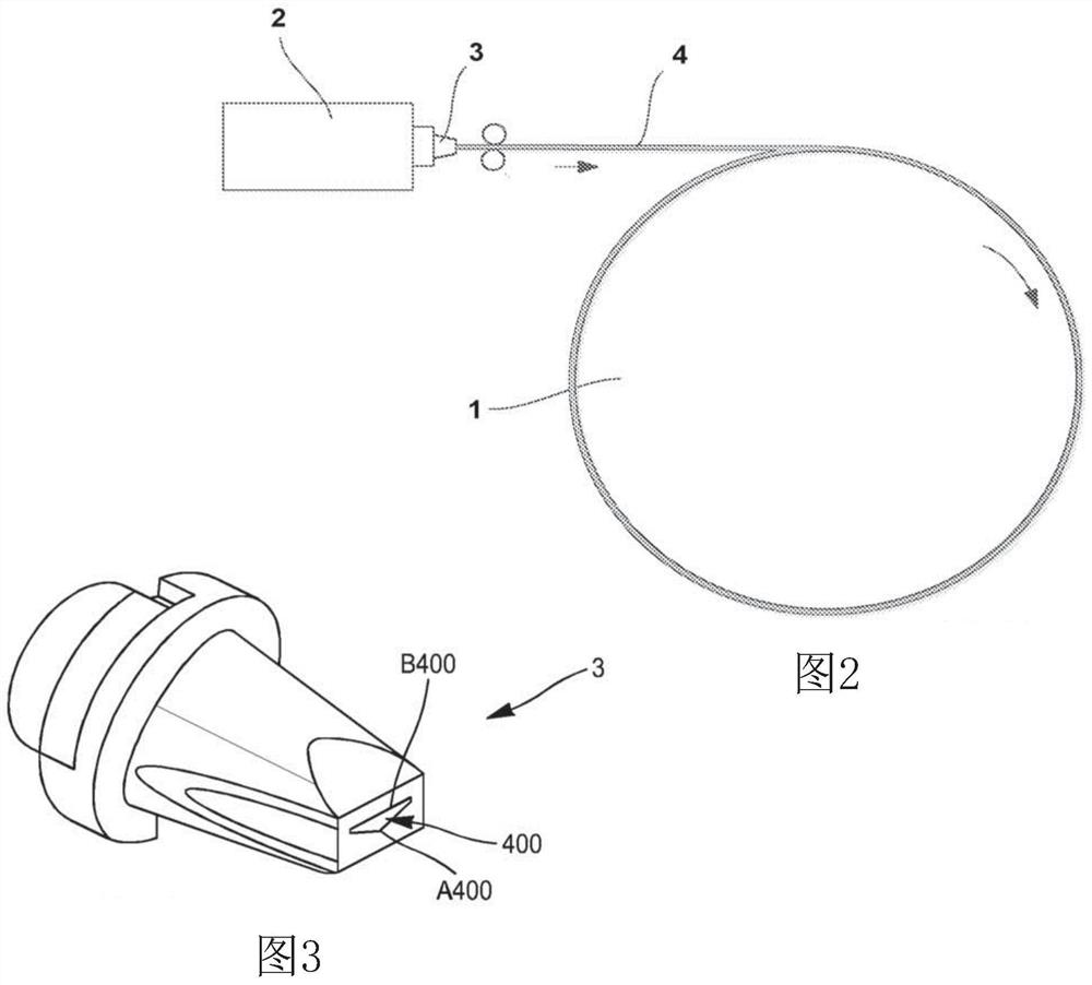
[0046] By way of example, a laying device for carrying out the method according to the invention comprises a forming drum rotated using a motorized assembly (not shown), and an extruder 2 leading to a nozzle 3, also as image 3 shown.

[0047] This assembly makes it possible to transport and wind the strip 4 on the forming drum 1 .

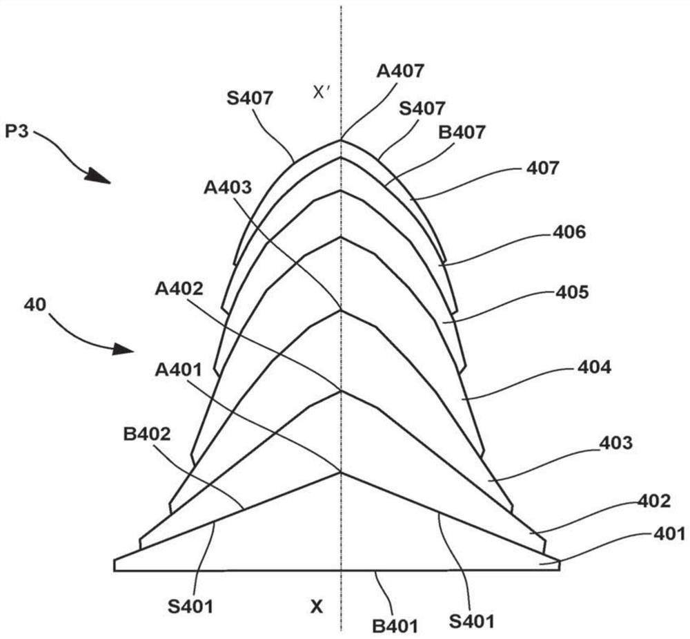
[0048] In step A, the strip 4 is fed. The profiles of the cross-sections 400, 410, 420, 430 of the strips are constant and known. In a particularly preferred manner, the strip is substantially triangular in cross-section, or even completely triangular, and preferably in the shape of an isosceles triangle.

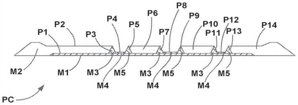
[0049] As mentioned above, the triangular shape of the section makes it easier and faster to produce profiled element parts P3, P5, P7, P9, P11, P13, in particular essentially triangular profiled element parts, which are particularly stable.

[0050] More specifically, choosing an isosceles triangle shaped strip section advantageously gives ...


PUM

PropertyMeasurementUnit
elongationaaaaaaaaaa

Abstract

The invention relates to a method of manufacturing a rubber profiled element (P3), in which the following steps are carried out: -step A: conveying a strip of unvulcanized rubber (4) with a given constant triangular cross-section, -step B: by changing the The strip is stretched at a rate of elongation such that the strip (4) has a reduced cross-section, - step C: by winding the reduced cross-section strip on itself on the rotating forming drum (1), And the profiled element (P3) is produced without changing the lateral position of the longitudinal axis of the strip.

Description

technical field [0001] The present invention relates to a method for producing shaped elements by winding. Background technique [0002] This method, widely used in the tire industry and known per se, involves the production of a tire green by winding a plurality of turns of unvulcanized rubber strips on a rotating building drum to form part of a forming element. [0003] The final profile of the part of the forming element is obtained by using a transverse winding device and moving transversely at a predetermined and variable pitch the point at which the strip is applied to the surface of the forming drum. [0004] A strip with a suitable cross-sectional profile can come from an unwinding device, or preferably an extrusion device located upstream of the transverse winding device. [0005] This method allows the production of more and more complex preforms, since it makes it possible to place forming element parts formed from different rubber compounds at various radial and...

Claims


Application Information

Patent Timeline
Patent Type & Authority Patents(China)
IPC IPC(8): B29C53/56B29D30/58
CPCB29K2021/006B29D30/58B29C53/562B29C48/92B29C48/022B29C48/07B29C48/12B29C48/0018B29C48/28B29C48/475B29C2948/9259B29C2948/926B29C2948/92857B29C2948/92933
Inventor C·贝萨克M·鲁比A·菲利奥尔
Owner MICHELIN & CO CIE GEN DES ESTAB MICHELIN
Why Eureka
Try Eureka