Disposable stripping type self-destruction syringe

A syringe and peel-off technology, applied in the field of disposable peel-off self-destruct syringes, can solve the problems of infection risk, patient pain, and easy vibration

Pending Publication Date: 2020-05-12
HUNAN LUZHOU HUIKANG DEV CO LTD
View PDF1 Cites 2 Cited by
  • Summary
  • Abstract
  • Description
  • Claims
  • Application Information

AI Technical Summary

Problems solved by technology

[0006] 1. The medicine injected in the hospital is generally quantitative. When the self-destructing syringe similar to the above is used, when the cartridge is in contact with the elastic snap ring, there is still a gap between the rubber plug and the bottom of the syringe barrel, that is, the medicine in the syringe is not It is completely finished, and to be completely finished, it is necessary to push the core rod hard, so that the cartridge overcomes the resistance with the elastic snap ring. When the medicine is finished, the cartridge and the elastic snap ring are stuck and self-destructed, and the core rod is pushed hard When it is used, it is easy to cause vibration, causing the injection needle to vibrate in the patient's body, causing pain to the patient, and may cause greater damage. However, if the resistance formed when the card holder and the elastic snap ring are stuck, it will inevitably cause the card holder and the elastic clip to be locked. The resistance after the ring is stuck is greatly reduced, and it will be difficult to play the anti-reuse function
[0007] 2. For some self-destructing syringes, although the design has made the card seat and the elastic snap ring get stuck, there is a greater locking force, but if the core rod is pulled out with force, the core rod can often be pulled out, causing it to be damaged. Rinse and use or be used as a toy by children, causing infection risk
[0008] 3. Since the barrel of the existing disposable syringe is still intact, in reality, some children pick it up to make water-shooting toys, and there are even unscrupulous vendors who recycle and reuse it privately.

Method used


Image

  • Disposable stripping type self-destruction syringe
  • Disposable stripping type self-destruction syringe
  • Disposable stripping type self-destruction syringe

Examples


Embodiment 2

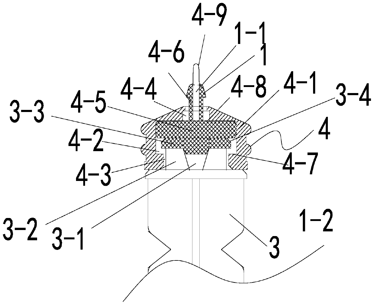
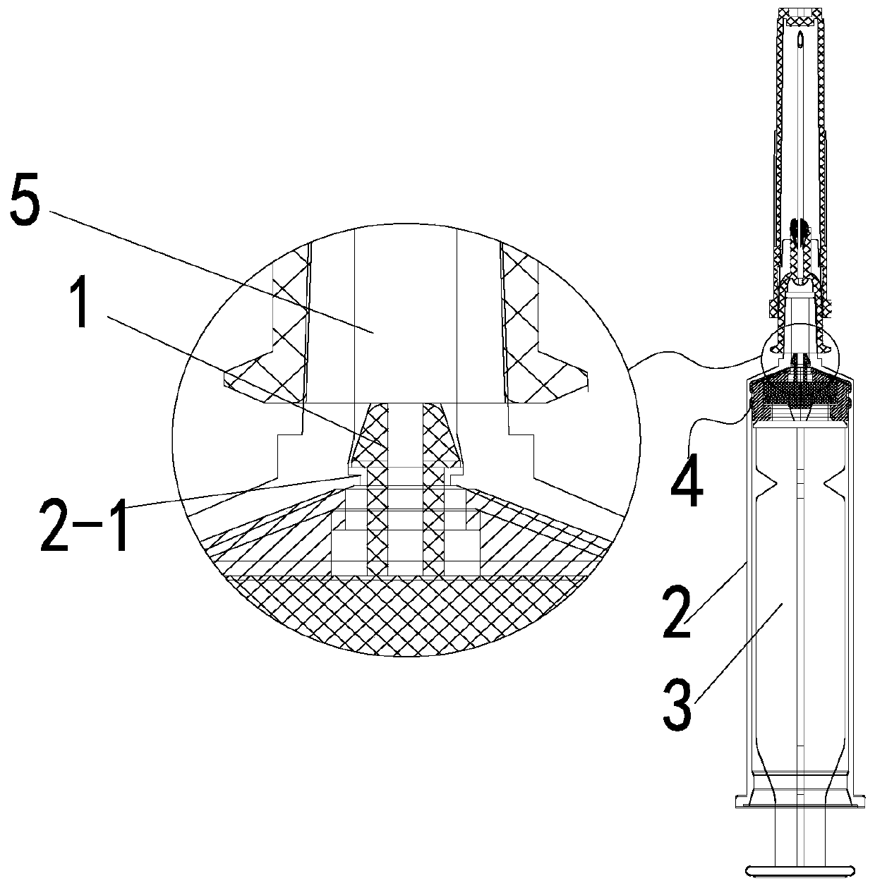
[0039] On the basis of Embodiment 1, in order to increase the locking performance of the tapered lock, the tapered lock 1 is formed with a locking maintenance mechanism. The specific locking maintenance mechanism is the connection block 4-9 that connects the top of the tapered lock 1 together or such as Figure 6 As shown, it includes a protrusion 4-10 protruding from the lower side of the tapered lock 1, and an annular locking strip 4-11 is formed on the protrusion of the annular protrusion 2-1 to cooperate with the protrusion 4-10.


PUM


Abstract

A disposable stripping type self-destruction syringe comprises a syringe barrel, a liquid outlet is fixed to the bottom of the syringe barrel, a core rod is inserted into the syringe barrel, the corerod is connected with a rubber plug structure, the core rod is detachably connected with the top end of the rubber plug structure, and conical lock catches are formed in the bottom end of the rubber plug structure in the circumferential direction, and the number of the conical lock catches is larger than or equal to 2. A hollow gap for separating the conical lock catches is formed in the middle ofthe bottom end of the rubber plug structure; an annular clamping protrusion matched with the conical lock catch is formed in the liquid outlet. The sum of the clamping force of the conical lock catchand the annular clamping protrusion is larger than the connecting force of the core rod and the rubber plug structure which is larger than the friction force between the rubber plug structure and theinjector barrel. When liquid medicine is injected, the rubber plug and the barrel are connected into a whole, and when the core rod is pulled back, the rubber plug structure is separated from the core rod, so that the injector is scrapped and cannot be used again, and the self-destruction function is achieved.

Description

Technical field: [0001] The invention relates to a disposable medical appliance, in particular to a disposable peel-off self-destruct syringe Background technique: [0002] Among the blood-borne diseases in the world, AIDS is the scariest one. According to the survey and statistics of WHO (World Health Organization), there are more than 36 million AIDS patients in the world, which has seriously threatened the health of human beings around the world. [0003] There are five main routes of transmission of HIV: ① Sexual transmission, the primary transmission route of the global AIDS epidemic, including genital, anal and oral sexual contact, the incidence rate is 70-80%; ② Transmission among intravenous drug users, Sharing drug injection equipment is a stable and continuously increasing risk factor, with an incidence rate of 3-10%; ③Transmission through blood products, using whole blood, red blood cells, fresh frozen plasma and platelets provided by a single blood donor, or usi...

Claims


Application Information

Patent Timeline
Patent Type & Authority Applications(China)
IPC IPC(8): A61M5/178A61M5/31A61M5/50
CPCA61M5/178A61M5/31A61M5/5066
Inventor 杨小英莫海罡
Owner HUNAN LUZHOU HUIKANG DEV CO LTD
Why Eureka
Try Eureka