Train and traction control system and method thereof

A traction control system and a technology for trains, applied in the field of rail transit, can solve the problems of long waiting time, affecting the comfort of trains with faults, ease of use and low efficiency of traction solutions, and achieve the effect of improving comfort and high efficiency

Inactive Publication Date: 2020-05-12
ZHUZHOU CSR TIMES ELECTRIC CO LTD
View PDF20 Cites 6 Cited by
  • Summary
  • Abstract
  • Description
  • Claims
  • Application Information

AI Technical Summary

Problems solved by technology

[0002] At present, the train mainly obtains electricity from the grid through the pantograph to maintain its normal operation. When the pantograph of the train fails or the train cannot obtain electricity from the grid due to other factors, it is determined that the train is faulty, and the faulty train cannot autonomously To run, it can only be towed by the rescue locomotive. Before the rescue locomotive arrives, the faulty train can only wait in place, and the waiting time is long, which makes the existing traction scheme low in ease of use and efficiency
[0003] In addition, only after the rescue locomotive drags the faulty train to the minimum speed threshold of rescue power generation, the faulty train can use its own device and control scheme to maintain the auxiliary load (such as air conditioning and cooling systems, etc.) to work. When the speed is between standstill and the minimum speed threshold of rescue power generation, the auxiliary load on the faulty train cannot be put into operation, which will seriously affect the comfort of the faulty train during the rescue return process during this period

Method used


Image

  • Train and traction control system and method thereof
  • Train and traction control system and method thereof
  • Train and traction control system and method thereof

Examples


Embodiment Construction

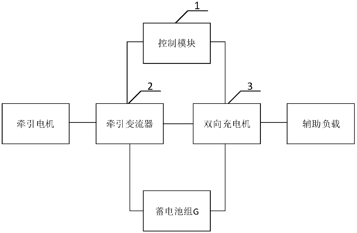
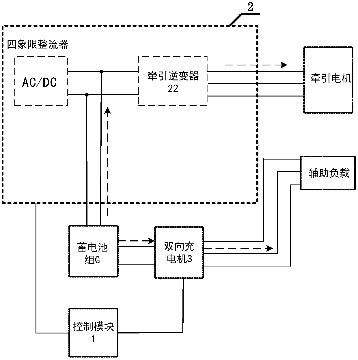
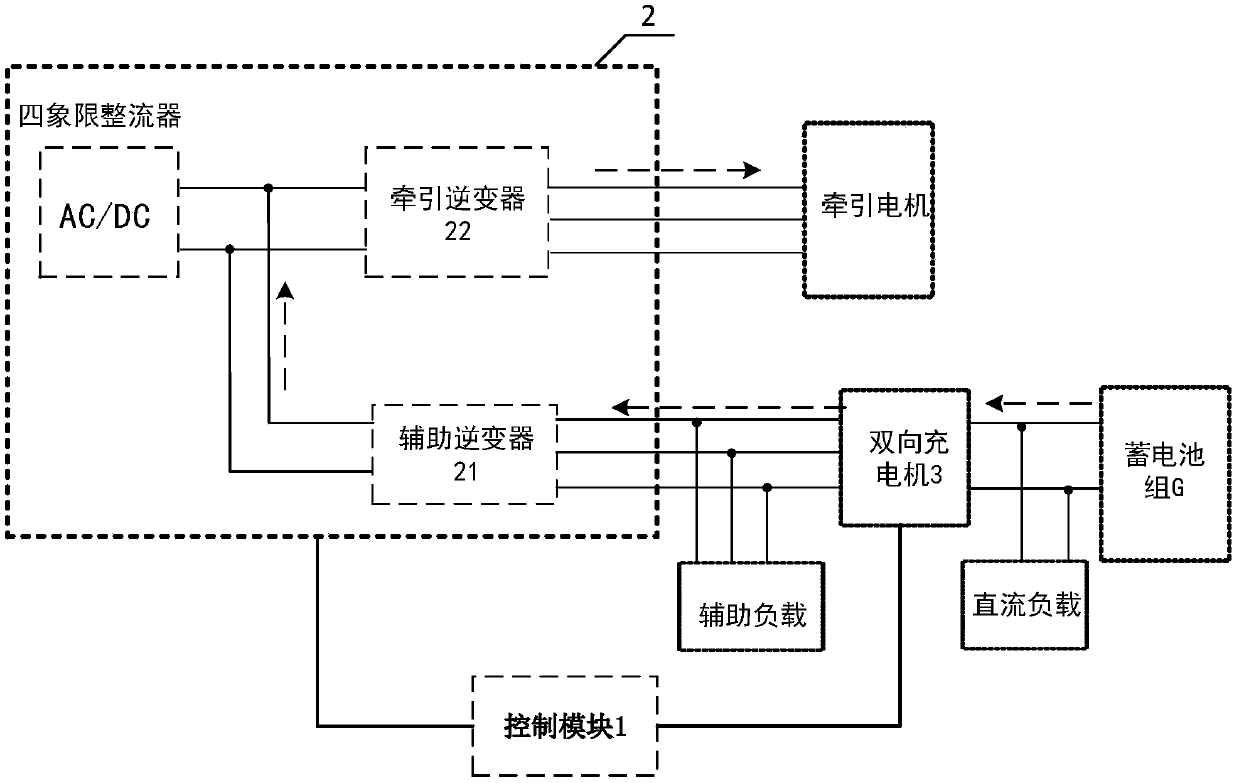
[0041] The core of the present invention is to provide a traction control system and method, which can start the emergency power supply through the existing storage battery on the train, so that the autonomous operation of the faulty train can be realized, and the efficiency is high. Comfort during the rescue return process; another core of the present invention is to provide a train including the above-mentioned traction control system.

[0042] In order to make the purpose, technical solutions and advantages of the embodiments of the present invention clearer, the technical solutions in the embodiments of the present invention will be clearly and completely described below in conjunction with the drawings in the embodiments of the present invention. Obviously, the described embodiments It is a part of embodiments of the present invention, but not all embodiments. Based on the embodiments of the present invention, all other embodiments obtained by persons of ordinary skill in...


PUM


Abstract

The invention discloses a traction control system, which comprises a control module for controlling a traction converter and a bidirectional charger to be started after receiving an emergency power supply instruction, a storage battery pack comprising a plurality of storage batteries and being used for outputting direct currents, a traction converter for converting the direct current output by thestorage battery pack into an alternating current and outputting the alternating current to a traction motor after receiving a traction instruction so as to drive a train to run through the traction motor, a bidirectional charger for converting the direct current output by the storage battery pack into an alternating current and outputting the alternating current to an auxiliary load and / or the traction converter after receiving the traction instruction or the auxiliary instruction to enable the auxiliary load to work conveniently. Emergency power supply is started through the existing storagebattery on the train, autonomous operation of the faulty train can be achieved, the efficiency is high; meanwhile, the storage battery provides power for the auxiliary load, so that the comfort of the faulty train in the rescue returning process is improved. The invention further discloses a traction control method and a train, which have the above beneficial effects.

Description

technical field [0001] The invention relates to the field of rail transportation, in particular to a train and its traction control system and method. Background technique [0002] At present, the train mainly obtains electricity from the grid through the pantograph to maintain its normal operation. When the pantograph of the train fails or the train cannot obtain electricity from the grid due to other factors, it is determined that the train is faulty, and the faulty train cannot autonomously To run, it can only be dragged by the rescue locomotive. Before the rescue locomotive arrives, the faulty train can only wait in place, and the waiting time is long, which makes the ease of use and efficiency of the existing traction scheme all low. [0003] In addition, only after the rescue locomotive drags the faulty train to the minimum speed threshold of rescue power generation, the faulty train can use its own device and control scheme to maintain the auxiliary load (such as air ...

Claims


Application Information

Patent Timeline
Patent Type & Authority Applications(China)
IPC IPC(8): B61L15/00B61L23/00B61C17/12
CPCB61L15/00B61L23/00B61C17/12
Inventor 陈东周坚曹金洲钟源段旭龙
Owner ZHUZHOU CSR TIMES ELECTRIC CO LTD
Why Eureka
Try Eureka