Suspension Insulator Replacement Job Kit

A technology for suspension insulators and work tools, applied in the field of suspension insulator replacement work kits, which can solve problems such as long working hours, affecting work quality, damage, etc., achieves a high degree of automation, reduces the risk of manual work, and is easy to operate Effect

Active Publication Date: 2021-01-01
ANHUI UNIVERSITY OF TECHNOLOGY
View PDF6 Cites 0 Cited by
  • Summary
  • Abstract
  • Description
  • Claims
  • Application Information

AI Technical Summary

Problems solved by technology

[0002] The amount of suspension insulator strings in the substation is huge, and the suspension insulator strings are in the open environment for a long time. Under the influence of environmental factors such as wind, sun and sun, the internal stress of the insulators will be unbalanced, resulting in low zero value of the insulators and even structural damage. As a result, the damage defects of the suspension insulator strings in the substation are increasing day by day
[0003] At present, there is no special replacement tool suitable for the suspension insulator strings in the station. When replacing the suspension insulator strings in the station, it can only be replaced by the traditional method, that is, the hand hoist is used to pull the wires and clamps, so that the suspension insulator strings are in the In the non-stressed state, the damaged insulators are disassembled and new insulators are installed. This method requires the cooperation of high-altitude operations and ground operations. Generally, three people are required to cooperate at high altitudes, and two people are required to connect on the ground. Take tools and insulators. This operation method takes a long time and increases the danger of workers working at heights. Moreover, the traction force of the lever hoist is not easy to control, and it is easy to generate overload traction, which will cause damage to the wires or clamps and affect the quality of work.

Method used


Image

  • Suspension Insulator Replacement Job Kit
  • Suspension Insulator Replacement Job Kit
  • Suspension Insulator Replacement Job Kit

Examples


Embodiment 1

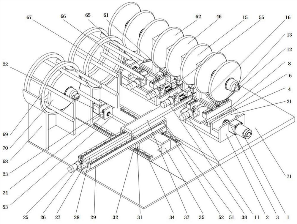
[0030] Such as figure 1 as shown, figure 1 It is a structural diagram of the suspension insulator replacement toolkit; the suspension insulator replacement operation toolkit of the present invention includes an insulator unloading device, an insulator replacement device, an insulator support device, an insulator storage bin and a general fixing platform 71 .

[0031] The insulator unloading device, the insulator replacement device, the insulator supporting device and the insulator storage bin are all fixedly arranged on the general fixed platform 71 . The insulator unloading device is symmetrically arranged on both sides of the general fixing platform 71; the insulator replacement device and the insulator supporting device are arranged in the middle of the insulator unloading device; the insulator storage bin is arranged on the side of the insulator unloading device .

[0032] The insulator unloading device completes the task of unloading the insulator string; the insulator re...

Embodiment 2

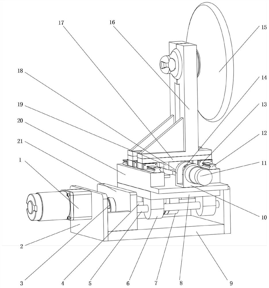
[0040] Such as figure 2 as shown, figure 2 It is a structural schematic diagram of the insulator unloading device; the insulator unloading device includes an unloading servo motor 1, an unloading motor adapter flange 2, an unloading coupling 3, an unloading lead screw 4, an unloading linear guide rail 5, and an unloading guide rail slider 6 , unloading screw nut 7, unloading clamping adapter flange 8, unloading fixed base plate 9, unloading clamping motor adapter flange 10, unloading clamping servo motor 11, unloading clamping linear guide rail 12, unloading clamping guide rail slide Block 13, unloading and clamping coupling 14, unloading clamping insulator 15, unloading jaw 16, unloading clamping jaw adapter flange 17, unloading and clamping two-way lead screw 18, unloading and clamping screw nut 19, unloading and clamping Fix the bottom plate 20 and unload the bearing seat 21.

[0041] The unloading fixed bottom plate 9 is placed horizontally, and the side is fixedly con...

Embodiment 3

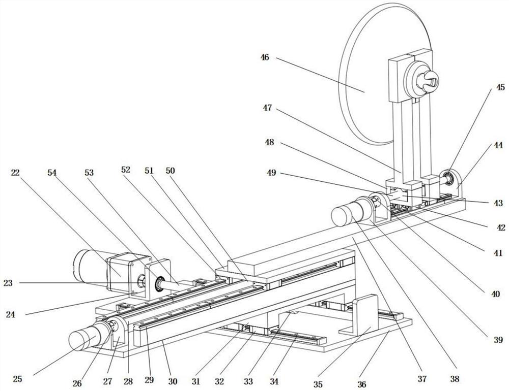
[0049] Such as image 3 as shown, image 3 It is a structural schematic diagram of the insulator replacement device; the insulator replacement device includes replacement of the transverse servo motor 22, replacement of the transverse coupling 23, replacement of the transverse motor adapter flange 24, replacement of the longitudinal servo motor 25, and replacement of the longitudinal coupling 26 , Replace the longitudinal motor adapter flange 27, replace the longitudinal screw 28, replace the longitudinal linear guide rail 29, replace the vertical fixed bottom plate 30, replace the horizontal and vertical transfer flange 31, replace the horizontal guide rail slider 32, replace the horizontal screw nut 33 , replace the horizontal linear guide rail 34, replace the lateral bearing seat 35, replace the fixed base plate 36, replace the clamping fixed base plate 37, replace the clamping servo motor 38, replace the clamping motor adapter flange 39, replace the clamping coupling 40, ...


PUM


Abstract

The invention discloses a suspension insulator replacement operation toolkit, and the toolkit comprises an insulator unloading device for completing an insulator string unloading task; an insulator replacing device which is used for completing the task of replacing the insulator sheet to be replaced; an insulator supporting device which is used for supporting the unloaded insulator sheet in the process of unloading and replacing the insulator; and an insulator storage bin which is used for storing damaged insulator pieces and brand-new insulator pieces. The insulator unloading device, the insulator replacing device, the insulator supporting device and the insulator storage bin are all fixedly arranged on the main fixing platform. The insulator unloading device, the insulator replacing device and the insulator supporting device are all driven by a driving device, so the driving device drives a lead screw to rotate and drives all the devices to move front and back to meet the requirementfor the freedom degree of all the devices; therefore, the insulator replacing operation is achieved, the automation degree is high, operation is easy, and the risk of manual operation is reduced.

Description

technical field [0001] The invention relates to the technical field of electric facility maintenance, in particular to a suspension insulator replacement work kit. Background technique [0002] The amount of suspension insulator strings in the substation is huge, and the suspension insulator strings are in the open environment for a long time. Under the influence of environmental factors such as wind, sun and sun, the internal stress of the insulators will be unbalanced, resulting in low zero value of the insulators and even structural damage. As a result, the damage defects of suspension insulator strings in substations are increasing day by day. [0003] At present, there is no special replacement tool suitable for the suspension insulator strings in the station. When replacing the suspension insulator strings in the station, it can only be replaced by the traditional method, that is, the hand hoist is used to pull the wires and clamps, so that the suspension insulator str...

Claims


Application Information

Patent Timeline
Patent Type & Authority Patents(China)
IPC IPC(8): H02G1/02
CPCH02G1/02
Inventor 高文斌黄琪王鹏
Owner ANHUI UNIVERSITY OF TECHNOLOGY
Why Eureka
Try Eureka