
Welding device with clamping structure for electric head

A welding device and clamping structure technology, applied in welding equipment, auxiliary devices, auxiliary welding equipment and other directions, can solve the problems of the welding machine not working normally, the applicability and practicability limitations, and easy to cause electric shock accidents, etc., to achieve the connection Convenient and fast, good practicability, good insulation performance

Active Publication Date: 2022-04-08
TIANSHENGQIAO TWO HYDROPOWER CO LTD
View PDF10 Cites 0 Cited by
  • Summary
  • Abstract
  • Description
  • Claims
  • Application Information

AI Technical Summary

Problems solved by technology

[0002] With the development of science and technology, the use of welding machines is becoming more and more extensive. Welding machines need to be connected to electricity during operation. There are many ways to connect to electricity. Among them, the traditional welding machine is connected to Wires, whose connection steps are cumbersome and easy to cause electric shock accidents, are also connected directly by plugging in the electric head. When this method touches the electric head, it is easy to cause the electric head to drop, thereby causing the welding machine to be powered off. Does not work properly, so applicability and usefulness are limited

Method used


Image

  • Welding device with clamping structure for electric head

Examples


Embodiment 1

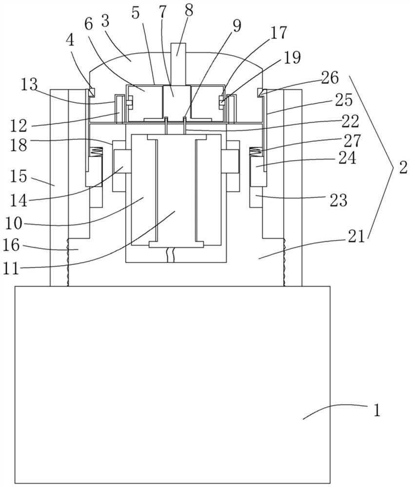
[0014] figure 1 A specific embodiment of the invention is shown in which figure 1 It is a structural schematic diagram of the present invention.

[0015] See figure 1 , a welding device with a connecting head clamping structure, comprising a welding device 1 (this is a conventional structure in the prior art) and a connecting head structure 2 fixed on the welding device, and the connecting head structure 2 includes a connecting head structure The electric seat 21 is provided with an electric connection socket 22 at the center of the electric connection seat, and three dovetail-shaped vertical chute 23 are evenly opened on the outer wall of the electric connection seat, and in the vertical chute A dovetail-shaped slider 24 is provided, and a locking plate 25 is fixed on the outer wall of the slider, and a buckle protrusion 26 is integrally formed on the top of the inner surface of the locking plate. A return spring 27 is fixed between the surface and the top wall of the vert...


PUM


Abstract

The invention discloses a welding device with a clamping structure of a connecting head, which comprises a welding device and a structure of a connecting head fixed on the welding device. The structure of the connecting head includes a connecting seat, and a connecting The electric plug-in column is provided with a dovetail-shaped slider in the vertical chute, a locking plate is fixed on the outer wall of the slider, and a locking protrusion is integrally formed on the top of the inner side of the locking plate. A return spring is fixed between the top surface and the top wall of the vertical chute, and an electric plug seat is also provided. There is an electric connection cavity in the electric connection socket, and a circular magnetic ring is arranged in the electric connection cavity. There is a conductive jack in the conductive plate, a magnet ring block is arranged in the electric connection seat, and a post holder is fixed in the center of the magnet ring block. The structure of the present invention is reasonably set up, and it is not easy for the electric head to fall off. At the same time, it is equipped with a magnet ring block and a circular magnetic ring, which can ensure the stability and applicability of the connection between the electric plug post and the conductive jack on the conductive plate. Strong and practical.

Description

technical field [0001] The invention belongs to the technical field of welding equipment, and in particular relates to a welding device with a clamping structure for a connecting head. Background technique [0002] With the development of science and technology, the use of welding machines is becoming more and more extensive. Welding machines need to be connected to electricity during operation. There are many ways to connect to electricity. Among them, the traditional welding machine is connected to Wires, whose connection steps are cumbersome and easy to cause electric shock accidents, are also connected directly by plugging in the electric head. When this method touches the electric head, it is easy to cause the electric head to drop, thereby causing the welding machine to be powered off. will not work properly, so applicability and usefulness are limited. Contents of the invention [0003] The purpose of the present invention is to provide a welding device with a reas...

Claims


Application Information

Patent Timeline
Patent Type & Authority Patents(China)
IPC IPC(8): B23K37/00
CPCB23K37/00
Inventor 郑多多
Owner TIANSHENGQIAO TWO HYDROPOWER CO LTD
Learn More