Front-in and front-out rotating box type horizontal split type garbage compression station

A garbage compression station, front-in front-out technology, applied in the direction of garbage transmission, garbage collection, loading/unloading, etc., can solve the problems of restricting the layout of garbage compression stations, inability to compress garbage, and reduce the efficiency of garbage compression, so as to reduce the occupied area Usable area, reasonable design, and small footprint

Pending Publication Date: 2020-05-19
FUJIAN QUNFENG MACHINERY
View PDF0 Cites 0 Cited by
  • Summary
  • Abstract
  • Description
  • Claims
  • Application Information

AI Technical Summary

Problems solved by technology

[0004] 1. The problem of large land use area. Most of this kind of garbage compression station is front-end feeding and rear-end discharging or side-end feeding and rear-end discharging. The front-end feeding often requires 7-9 meters of space for the collection vehicle to transfer , the back-end discharge needs at least 13.5-16 meters of hook-arm truck transfer space, plus the occupied space of the equipment itself, a large land area is required to arrange a garbage compression station, which greatly restricts the waste compression station. layout
[0005] 2. It takes a long time to replace the garbage container, and it needs to be loaded and unloaded twice at a time. However, it takes a certain amount of time for the hook-arm truck to load and unload the garbage container, making it impossible to compress the garbage at the stage of replacing the garbage container. operation, resulting in a reduction in the efficiency of garbage compaction

Method used


Image

  • Front-in and front-out rotating box type horizontal split type garbage compression station
  • Front-in and front-out rotating box type horizontal split type garbage compression station
  • Front-in and front-out rotating box type horizontal split type garbage compression station

Examples


Embodiment Construction

[0026] The present invention will be further described below in conjunction with the accompanying drawings and specific embodiments.

[0027] The directional terms mentioned in the present invention, such as: up, down, inside, outside, etc., are only for reference figure 1 direction. Accordingly, the directional terms used are for illustration only and not for limitation of the present invention.

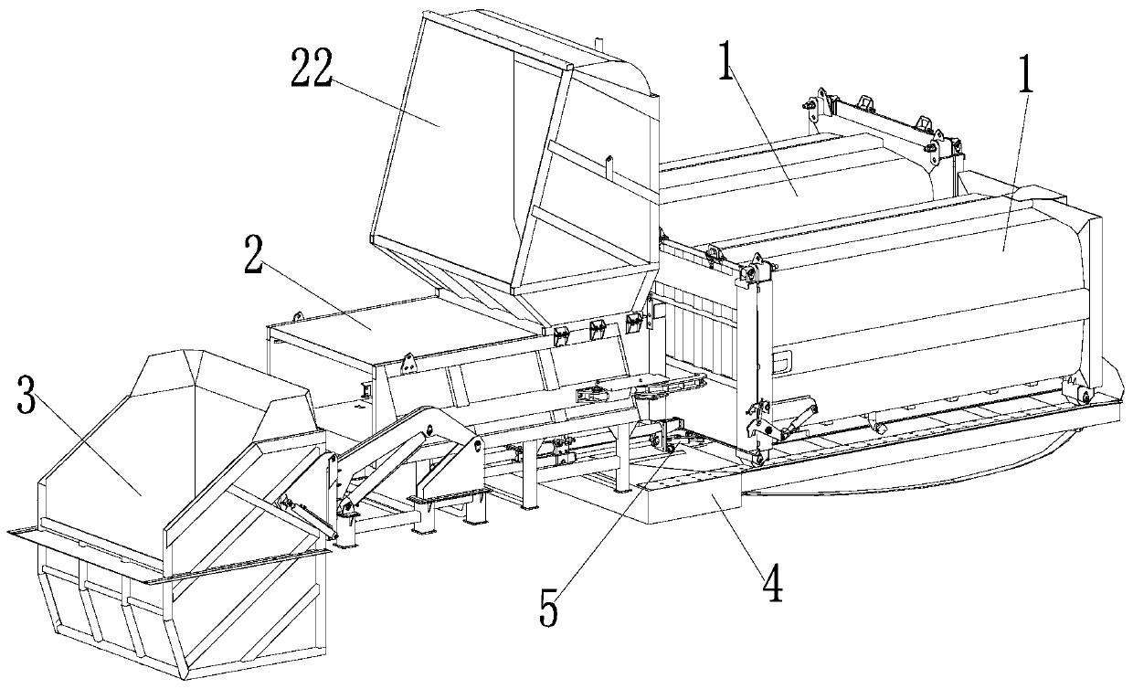
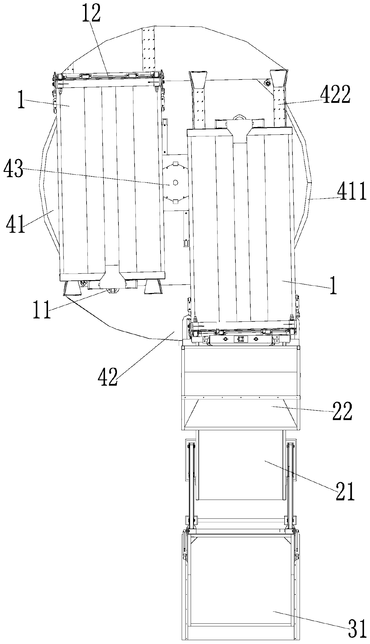
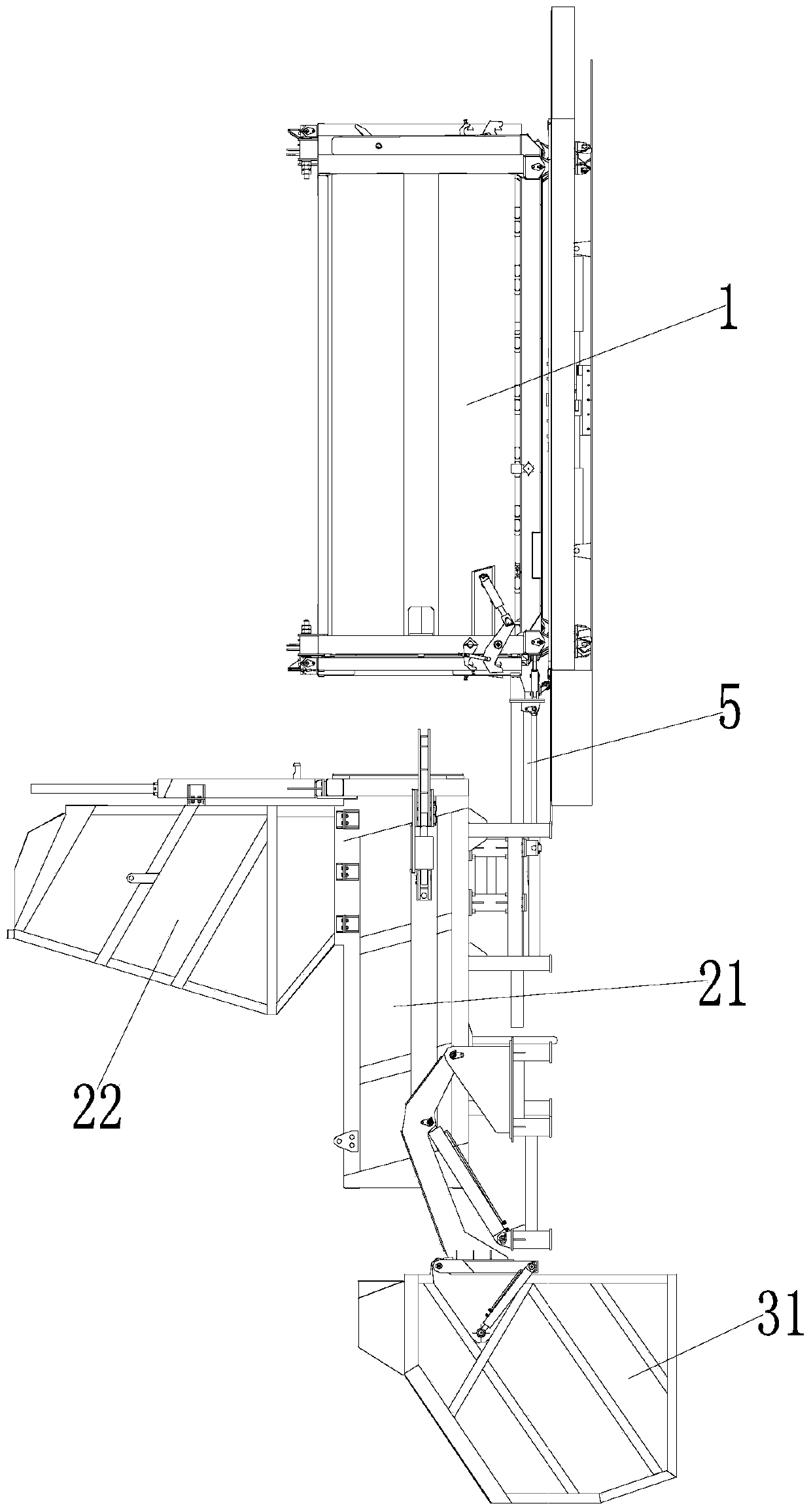
[0028] Such as Figure 1-4As shown, a forward-and-front-out transfer box type horizontally split garbage compression station includes a garbage container 1 for collecting garbage, a garbage compression device 2 for compressing garbage into the garbage container 1, and a garbage compression device 2 for putting garbage into The feeding mechanism 3 in the garbage compression device 2 also includes a turntable platform 4, and the turntable platform 4 includes a fixed base 41, a rotating platform 42, a rotating device 43, and a connecting plate 44, and the fixed base 41 is pre-embedde...


PUM


Abstract

The invention relates to the technical field of garbage compression equipment manufacturing, in particular to a front-in and front-out rotating box type horizontal split type garbage compression station. The garbage compression station comprises garbage containers, a garbage compression device and a feeding mechanism, and further comprises a rotating box platform, wherein the rotating box platformcomprises a fixed base, a rotating platform, a rotating device and a connecting plate; the fixed base is fixed to the ground through an embedded part, the rotating device is arranged on the fixed base, and the rotating platform is connected with the rotating device through a connecting plate; and two placing platforms used for placing the garbage containers are arranged on the rotating platform,and the two placing platforms move along with movement of the rotating device, so that the garbage containers rotate by 180 degrees. The garbage compression station is novel in structure, reasonable in design and small in occupied use area, the operation of unloading an empty garbage container and then placing the empty garbage container on the placing platform is not needed, the time for replacing the garbage container is shortened, and therefore the garbage compression efficiency is greatly improved.

Description

technical field [0001] The invention relates to the technical field of garbage compression equipment manufacturing, in particular to a forward-front-out rotary box type horizontal split garbage compression station. Background technique [0002] Garbage compressor is one of the main equipment to achieve garbage compression and volume reduction, and it is also the main processing equipment of the garbage transfer station. It is a machine controlled by the hydraulic system to compress the collected garbage to reduce the volume of garbage. [0003] Among them, the horizontal split garbage compression station is a relatively large garbage compressor, which compresses the collected garbage into a garbage container, and then transports it away with a hook-arm truck for further processing. However, the existing horizontal split garbage compression station has the following problems: [0004] 1. The problem of large land use area. Most of this kind of garbage compression station is ...

Claims


Application Information

Patent Timeline
Patent Type & Authority Applications(China)
IPC IPC(8): B65F9/00
CPCB65F9/00
Inventor 洪松彬雷鸿辉黄佳忠朱汉榕卓东武骆旭东潘怡芳
Owner FUJIAN QUNFENG MACHINERY
Why Eureka
Try Eureka