Novel straight beam integration module

A technology of integrated modules and straight beams, applied in the field of elevators, can solve problems such as large space occupation and complicated installation, and achieve the effects of reducing installation space, ensuring normal use, and enhancing effective protection

Pending Publication Date: 2020-05-19
杭州宝宸科技有限公司
View PDF0 Cites 0 Cited by
  • Summary
  • Abstract
  • Description
  • Claims
  • Application Information

AI Technical Summary

Problems solved by technology

[0003] At present, the safety gear and the guide shoe are independent parts, which are bolted to the straight beam or the bottom bracket of the car frame, which takes up a lot of space and is complicated to install

Method used


Image

  • Novel straight beam integration module
  • Novel straight beam integration module
  • Novel straight beam integration module

Examples


Embodiment 1

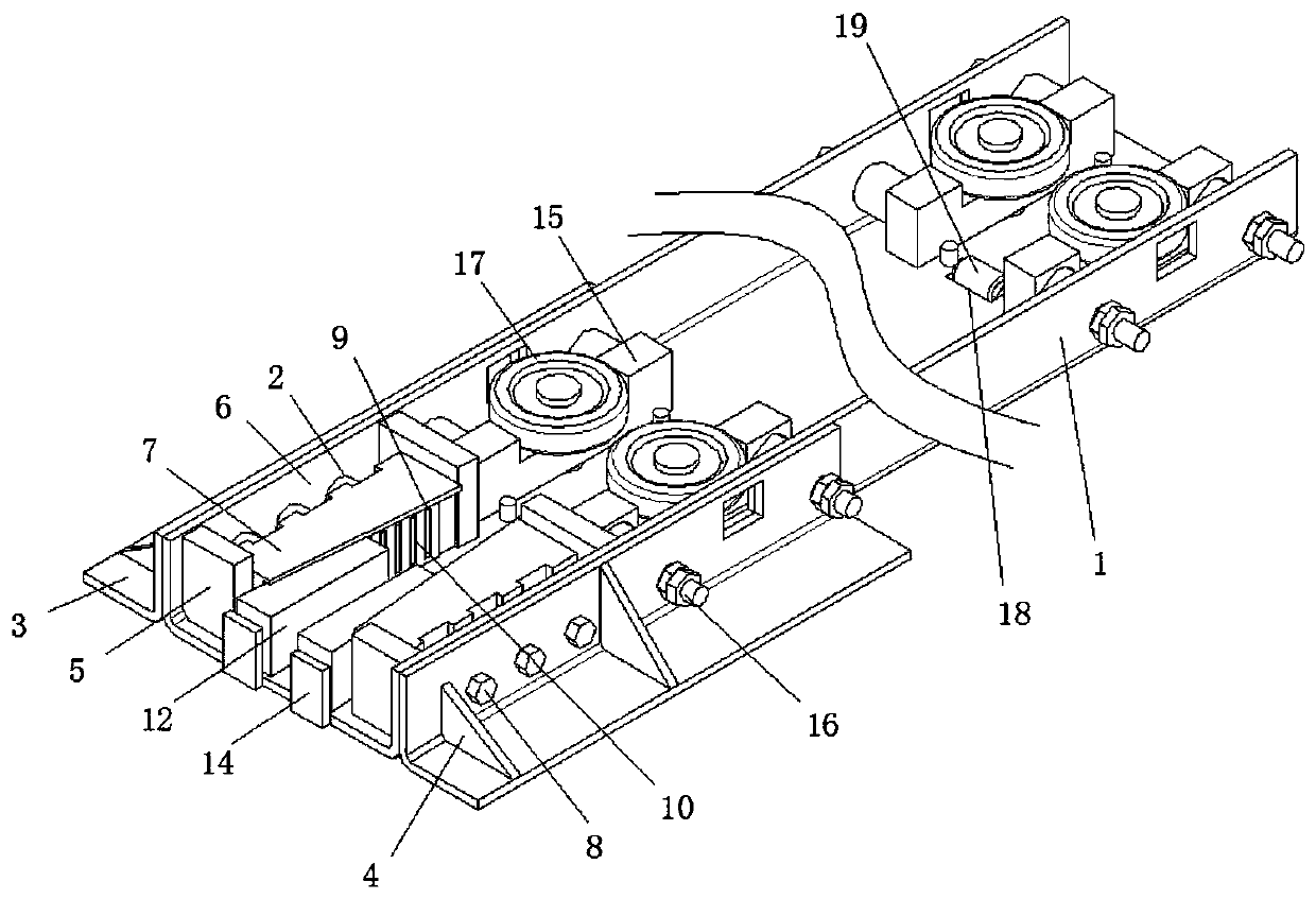
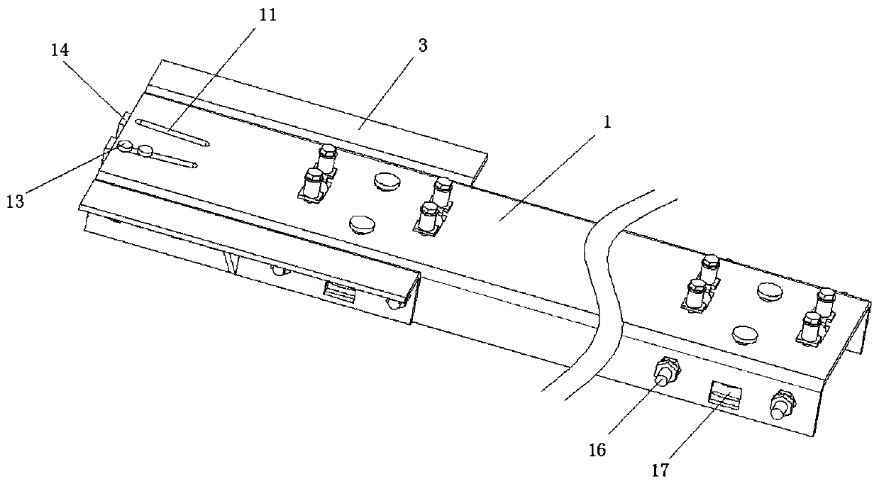
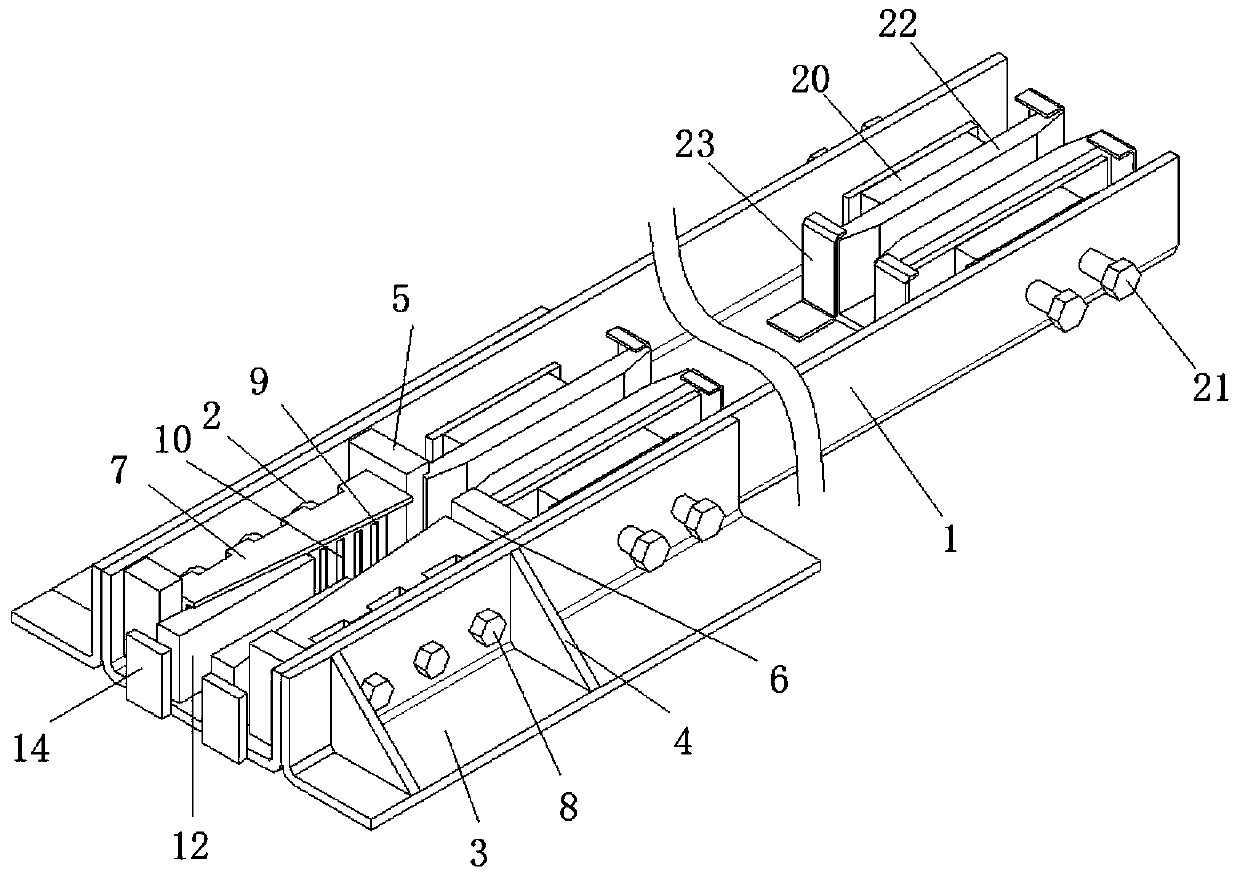
[0039] refer to Figure 1-3, a new type of straight beam integrated module, including a beam body 1, a braking mechanism and a guiding mechanism, one end of the beam body 1 is fixedly installed with a corner plate 3 on both sides of the beam body 1, and the upper surface of the corner plate 3 is fixedly installed with a reinforcement Rib 4, reinforcement plate 5 is fixedly installed on the inner wall of beam body 1, guide wedges 7 are symmetrically arranged on the braking mechanism, and guide wedges 7 are located between reinforcement plates 5;

[0040] Further, the four reinforcing plates 5 are distributed symmetrically around the axis of the beam body 1, the surface of the reinforcing plate 5 and the inner wall of the beam body 1 are provided with a safety locking cavity 6, and the inner wall of the safety locking cavity 6 is connected to the guide wedge The surface of 7 is slidingly connected, and the two guide wedges 7 are symmetrically distributed around the axis of the b...

Embodiment 2

[0052] refer to Figure 1-3 , a new type of straight beam integrated module, including a beam body 1, a braking mechanism and a guiding mechanism, one end of the beam body 1 is fixedly installed with a corner plate 3 on both sides of the beam body 1, and the upper surface of the corner plate 3 is fixedly installed with a reinforcement Rib 4, reinforcement plate 5 is fixedly installed on the inner wall of beam body 1, guide wedges 7 are symmetrically arranged on the braking mechanism, and guide wedges 7 are located between reinforcement plates 5;

[0053] Further, the four reinforcing plates 5 are distributed symmetrically around the axis of the beam body 1, the surface of the reinforcing plate 5 and the inner wall of the beam body 1 are provided with a safety locking cavity 6, and the inner wall of the safety locking cavity 6 is connected to the guide wedge The surface of 7 is slidingly connected, and the two guide wedges 7 are symmetrically distributed around the axis of the ...


PUM


Abstract

The invention belongs to the technical field of elevators, and particularly relates to a novel straight beam integration module. A beam body, a braking mechanism and a guiding mechanism are included.Strengthening ribs and strengthening plates are arranged at one end position of the beam body. The braking mechanism is symmetrically provided with guiding wedge blocks, and the guiding wedge blocks are located between the strengthening plates. The guiding mechanism comprises a first fixing base, and the first fixing base conducts positioning guiding through a cylinder bolt. According to the novelstraight beam integration module, through the arrangement of the braking mechanism, the effect of guaranteeing elevator lifting safety is achieved, meanwhile, the braking mechanism is integrally arranged in the beam body, accordingly, the installing space is reduced, and meanwhile the strengthening ribs and the strengthening plates on the beam body can enhance effective protection on the brakingmechanism. Through the arrangement of the guiding mechanism, the braking mechanism can be buckled to a guide rail of an elevator shaft, the braking mechanism does not slide out of the guide rail of the elevator shaft, safety is improved, normal usage of the braking mechanism is guaranteed, meanwhile, the occupied space is small, and the braking mechanism is arranged in the beam body and can be protected.

Description

technical field [0001] The invention relates to the technical field of elevators, in particular to a novel straight beam integrated module. Background technique [0002] Elevator refers to the permanent transportation equipment that serves several specific floors in the building, and its car runs on at least two rigid rails that are perpendicular to the horizontal plane or at an inclination angle of less than 15° from the plumb line. [0003] At present, the safety gear and the guide shoe are independent parts, which are bolted to the straight beam or the bottom bracket of the car frame, which takes up a lot of space and is complicated to install. Contents of the invention [0004] Based on the technical problems that the existing safety gear and guide shoes are independent parts, bolted to the straight beam or car frame bottom bracket, occupying a large space and complicated to install, the present invention proposes a new type of straight beam integrated module. [0005...

Claims


Application Information

Patent Timeline
IPC IPC(8): B66B5/22B66B7/02B66B7/04
CPCB66B5/22B66B7/023B66B7/027B66B7/046
Inventor 周晓雪
Owner 杭州宝宸科技有限公司
Why Eureka
Try Eureka