A connecting rod type rock confining pressure applying device and rock sample block confining pressure applying method

A technology for applying devices and rock samples, which is applied in the direction of measuring devices, test machinability, instruments, etc., can solve problems such as lack of confining pressure simulation capabilities, and achieve the effects of reducing test costs, improving equipment utilization, and simple structure

Active Publication Date: 2022-05-13
XIANGTAN UNIV
View PDF16 Cites 0 Cited by
  • Summary
  • Abstract
  • Description
  • Claims
  • Application Information

AI Technical Summary

Problems solved by technology

Furthermore, considering that some research topics related to deep rock formations need to simulate the state of rock lateral confining pressure, at the same time, a sufficient size of the rock surface to be cut should be reserved for cutting and breaking by tools, or pasting and laying out test equipment, etc. Moreover, a large number of relevant existing test benches do not have the ability to simulate confining pressure. Therefore, without changing the main structure of the original test bench, without additionally adding complex and huge hydraulic systems, and without using bath oil pressurization with high reliability and sealing requirements Under the premise of the method, an economically feasible device for applying rock confining pressure under various rock-breaking conditions of the rock-breaking tool obviously has huge economic effects and market potential.

Method used


Image

  • A connecting rod type rock confining pressure applying device and rock sample block confining pressure applying method
  • A connecting rod type rock confining pressure applying device and rock sample block confining pressure applying method
  • A connecting rod type rock confining pressure applying device and rock sample block confining pressure applying method

Examples


specific Embodiment 1

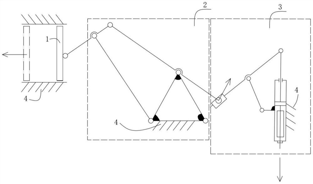
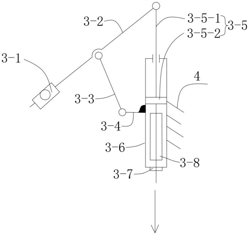
[0090] like Figure 1 to Figure 5 , Figure 10 Shown is the accompanying drawing of a specific embodiment 1 of a connecting rod type rock confining pressure applying device of the present invention. like figure 1 As shown, it is a connecting rod type rock confining pressure application device of the present invention, which includes a loading plate 1, a horizontal luffing mechanism 2, a fixed block mechanism 3, a heat collecting and conducting block 3-8, and a heating element (not shown). Features:

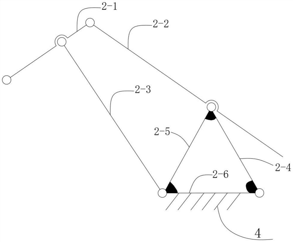
[0091] The horizontal luffing mechanism includes the active rocker 2-2, the driven rocker 2-3 and the transition link 2-1; the active rocker 2-2 and the driven rocker 2-3 are connecting rods; the transition link 2-1 is a connecting rod; driven by the active rocker 2-2, the power passes through the transition connecting rod 2-1, so that the driven rocker 2-3 swings around the frame 4 with the active rocker 2-2 ;During this process, the rod end at the transition link 2-1 always ...


PUM

PropertyMeasurementUnit
elastic modulusaaaaaaaaaa

Abstract

The invention provides a connecting rod type rock confining pressure applying device and a rock sample block confining pressure applying method; the device includes a loading plate, a horizontal luffing mechanism, a fixed block mechanism, a heat collecting and conducting block, and a heating element; the loading plate, The horizontal luffing mechanism is sequentially connected with the fixed block mechanism; the threaded connecting rod in the fixed block mechanism is embedded in the guide tube, and its end section moves through the guide tube; the loading plate is facing the upper side of the rock sample block and is connected with The rod end of the horizontal luffing mechanism is connected through a high pair; when the threaded connecting rod is firmly connected with the guide cylinder at room temperature, the loading plate is in close contact with the loading side; The screw is heated from room temperature to the specified temperature; the loading plate contacts and squeezes the loading side of the upper part of the rock sample block by using the huge tensile force generated by the cold shrinkage of the rod body to generate a given size of confining pressure. The invention is simple in structure, stable and reliable, economical and practical, and convenient to operate, and is suitable for various research fields of deep rock formations.

Description

technical field [0001] The invention belongs to the intersecting field of tunnel engineering and geotechnical engineering, and relates to a rock confining pressure applying device, in particular to a standard TBM hob (disc hob) realized by a connecting rod mechanism. The rock confining pressure application device used by the wire cutting test bench (hereinafter referred to as the TBM standard wire cutting test bench) is used to simulate the rock confining pressure state under various rock breaking conditions of the rock breaking tool. Background technique [0002] The rock mass existing in the formation, especially the natural rock mass in the deep rock stratum, has a certain in-situ stress (also called rock mass confining pressure) due to the influence of gravity, plate movement, and crustal contraction. The confining pressure of the rock mass affects the physical and mechanical properties of the rock itself, the rock breaking / destruction mechanism, etc., as well as the roc...

Claims


Application Information

Patent Timeline
Patent Type & Authority Patents(China)
IPC IPC(8): G01N3/58G01N3/02
CPCG01N3/58G01N3/02G01N2203/0232G01N2203/0256
Inventor 张魁钟世燊李艳
Owner XIANGTAN UNIV
Why Eureka
Try Eureka