
Drainage type fire-resistant groove box

A technology of refractory tanks and drainage holes, applied in the direction of electrical components, etc., can solve the problems of cables being easily burned by fire, external fires, and cable fires, and achieve the effect of preventing the fire from spreading outward and preventing the spread of fire

Pending Publication Date: 2020-05-19
GUANGDONG POWER GRID CO LTD +1
View PDF1 Cites 0 Cited by
  • Summary
  • Abstract
  • Description
  • Claims
  • Application Information

AI Technical Summary

Problems solved by technology

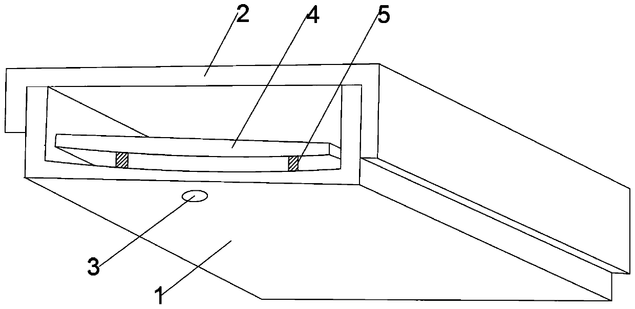
[0004] For this reason, the embodiment of the present invention provides a drainage-type refractory tank box to solve the problem in the prior art that the cables in the fire-resistant tank box are easily burned by fire due to the installation of drainage holes, or the cables catch fire and cause external fires.

Method used


Image

  • Drainage type fire-resistant groove box
  • Drainage type fire-resistant groove box
  • Drainage type fire-resistant groove box

Examples


Embodiment Construction

[0026] In order to make the purpose, features and advantages of the present invention more obvious and understandable, the technical solutions in the embodiments of the present invention will be clearly and completely described below in conjunction with the accompanying drawings in the embodiments of the present invention. Obviously, the following The described embodiments are only some, not all, embodiments of the present invention. Based on the embodiments of the present invention, all other embodiments obtained by persons of ordinary skill in the art without making creative efforts belong to the protection scope of the present invention.

[0027] The technical solutions of the present invention will be further described below in conjunction with the accompanying drawings and through specific implementation methods.

[0028] In the description of the present invention, it should be understood that the orientations or positional relationships indicated by the terms "upper", "...


PUM


Abstract

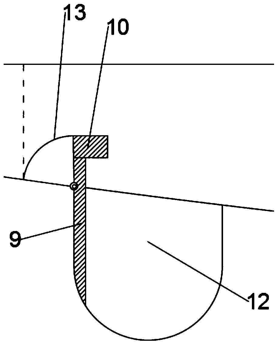
The embodiment of the invention discloses a drainage type fireproof groove box. The drainage type fireproof groove box comprises a U-shaped main body mounted on a wall, and a U-shaped cover plate fixedly nested on the U-shaped main body, a drainage hole penetrating through the outside is formed in the lower bottom surface of the U-shaped main body in the gravity direction, a baffle capable of falling off under the action of gravity to seal and cover the drainage hole is arranged in the U-shaped main body, and baffles are erected on the two sides of the drainage hole through hot melting supporting strips which are melted when heated; by means of the hot melting supporting strips and the baffles, water in the U-shaped body can flow to the outside from the drainage holes in a barrier-free mode; when a fire occurs outside the U-shaped main body, the baffles fall off under the action of gravity, and the drainage hole is covered; when a cable in the U-shaped main body is on fire, the bafflesseal and cover the drainage hole, so that fire can be prevented from spreading outwards; according to the drainage type fireproof groove box, through the hot melting supporting strips and the baffles, while the drainage function of the drainage holes is reserved, certain isolation capacity is achieved for fire behaviors, and fire spreading can be prevented.

Description

technical field [0001] The embodiment of the present invention relates to the technical field of cable troughs, in particular to a drainage type refractory trough. Background technique [0002] Cable tray boxes are usually made of high temperature and fire resistant materials. As a common support and protection device for cable laying in the power supply system of electrical equipment, the cable trough box plays a role in protecting and guiding the cables laid in the cable trough box. However, in rainy days, rainwater will accumulate in the cable trough box, and the cables will be easily damaged when soaked in water, resulting in safety accidents such as electric leakage and short circuit. [0003] In the prior art, the above-mentioned problems are usually solved by using drainable cable trough boxes, such as the utility model with application number 201720894788.4, which isolates and fixes the cables through the partition cover, and then sets drainage grooves and drainage ...

Claims


Application Information

Patent Timeline
IPC IPC(8): H02G3/10H02G3/08
CPCH02G3/088H02G3/10
Inventor 卢润波庾润铭萧耀华伦洪标
Owner GUANGDONG POWER GRID CO LTD
Learn More