Automatic control deluge system

An electric control valve and deluge technology, which is applied in fire rescue and other directions, can solve the problems of poor reliability and low degree of automation, and achieve the effects of convenient maintenance and management, improved automation capabilities, and reduced fire losses

Pending Publication Date: 2022-03-25
GUANGDONG POWER GRID CO LTD +1
View PDF9 Cites 0 Cited by
  • Summary
  • Abstract
  • Description
  • Claims
  • Application Information

AI Technical Summary

Problems solved by technology

[0005] The purpose of the present invention is to provide an automatic control deluge system to

Method used


Image

  • Automatic control deluge system

Examples


Example Embodiment

[0028] Example one

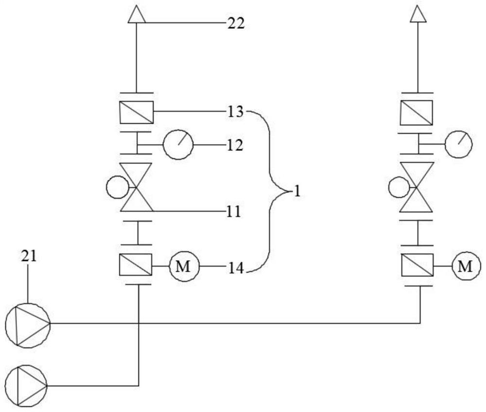
[0029] This embodiment provides an automatic control of rain shower system, such as figure 1 As shown, the automatic control rain shower system includes a rain shower valve assembly 1, a spray assembly, and an automatic fire device, and the rain shower valve assembly 1 includes a rain radius alarm valve 11 and a pressure switch 12, a rain alarm valve 11 and a pressure switch 12 via The pipe connection, the pressure switch 12 is configured to detect the pressure size within the conduit; the sprinkler assembly includes the sprinkler head 22 and the fire pump set 21, the sprinkler head 22 and the pressure switch 12 are connected by a pipe, the fire pump set 21 and the rain alarm valve 11 Through the pipe connection; the automatic fire device includes an electrically connected smoke sensor and a control member, the smoke sensor can detect the smoke concentration in the building, the rain radius alarm valve 11 and the pressure switch 12 are electrically connected t...

Example Embodiment

[0040] Example 2

[0041] This embodiment provides another automatic control of the rain shower system, and the basic structure of the automatic control rain shower system provided in this embodiment is the same as that of the embodiment, and there is only a difference in partial structure. This embodiment will only be described only for a different configuration in accordance with an embodiment.

[0042] In this embodiment, the rain whirlwell valve assembly 1 further includes a manual control valve 13, and the manual control valve 13 is provided between the pressure switch 12 and the sprinkler head 22, and the manual control valve 13 is connected to the pressure switch 12 and the sprinkler head 22 via a pipe. By providing the manual control valve 13, when the sprinkler nozzle 22 is maintained, the operator can turn off the manual control valve 13 to prevent the manual control valve 13 to improve the maintenance efficiency. It should be noted that the manual control valve 13 is in...


PUM


Abstract

The invention belongs to the technical field of water spraying fire extinguishing devices, and discloses an automatic control deluge system. The automatic control deluge system comprises a deluge valve assembly, a spraying assembly and an automatic fire detection device, the deluge valve assembly comprises a deluge alarm valve and a pressure switch, the deluge alarm valve and the pressure switch are connected through a pipeline, and the pressure switch is configured to be capable of detecting the pressure in the pipeline; the spraying assembly comprises a sprinkler head and a fire pump set, the sprinkler head is connected with the pressure switch through a pipeline, and the fire pump set is connected with the deluge alarm valve through a pipeline; the automatic fire detection device comprises a smoke sensor and a control part which are electrically connected, the smoke sensor can detect the smoke concentration in the building, the deluge alarm valve and the pressure switch are electrically connected with the control part, the fire pump set is electrically connected with the control part, and the control part can control the fire pump set to be started when the pressure exceeds a preset threshold value. The automatic control deluge system provided by the invention has the advantages of high automation capability, high reliability and convenience in maintenance and management.

Description

technical field [0001] The invention relates to the technical field of sprinkler fire extinguishing devices, in particular to an automatic control deluge system. Background technique [0002] The sprinkler system can detect fire, alarm and spray water to extinguish fire. It is the most widely used and cheap fire extinguishing system in the world today. The commonly used sprinkler system includes components such as sprinkler head, alarm valve group and water flow indicator. The sprinkler system can spray water on the fire parts when a fire breaks out. There are many types of sprinkler systems, which can be divided into wet system, dry system, pre-action system, deluge system and water curtain system in terms of function. [0003] Deluge systems are usually used in buildings where fires are prone to spread rapidly, especially for fire extinguishing of power systems. For large transformers, the technical specifications require the installation of a deluge system for spraying ...

Claims


Application Information

Patent Timeline
IPC IPC(8): A62C31/00A62C31/05A62C31/28A62C37/40
CPCA62C31/005A62C31/05A62C31/28A62C37/40
Inventor 卢润波周鹏威
Owner GUANGDONG POWER GRID CO LTD
Why Eureka
Try Eureka