Flexible rope-driven elbow joint exoskeleton robot with compensation device
An exoskeleton robot and compensation device technology, applied in gymnastics equipment, passive exercise equipment, sports accessories, etc., can solve the problems of single-function auxiliary rehabilitation equipment, uncomfortable rehabilitation training, etc., achieve convenient wearing and carrying, increase transmission flexibility, The effect of increasing comfort
- Summary
- Abstract
- Description
- Claims
- Application Information
AI Technical Summary
Problems solved by technology
Method used
Image
Examples
specific Embodiment approach 1
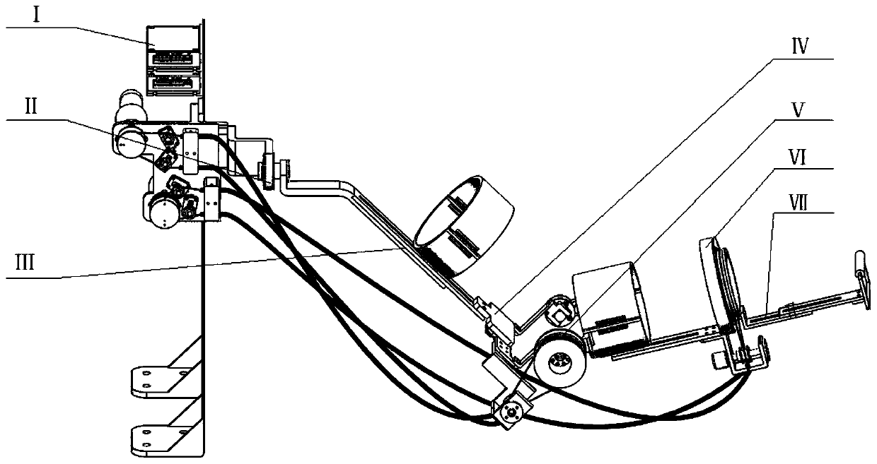
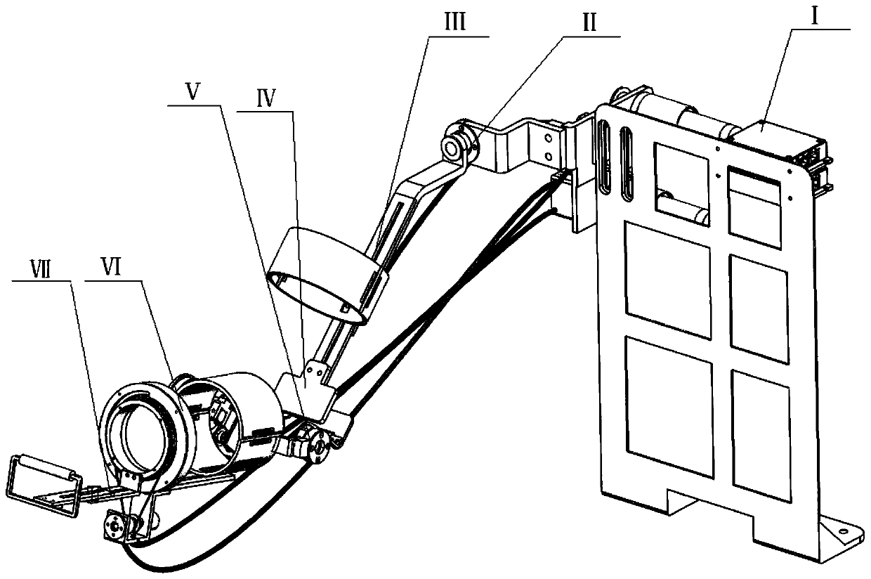
[0022] Specific implementation mode one: combine Figure 1-Figure 12 Describe this embodiment, a flexible rope-driven elbow-joint exoskeleton robot with a compensation device described in this embodiment, which includes a backboard 2, a drive device I, a shoulder joint device II, and a large arm device III with length adjustment, Dislocation compensation device IV, elbow flexion and extension device V, elbow rotation device VI, forearm device VII with length adjustment and two sets of Bowden wires, drive device I is installed on one side of the back plate 2, shoulder joint device II is installed on one side of the backboard 2, shoulder joint device II, arm device III with length adjustment, misalignment compensation device IV, elbow flexion and extension device V, elbow rotation device VI and small arm device with length adjustment The arm device VII is connected sequentially, one end of two groups of Bowden wires is connected with the driving device I, the other end of one gr...
specific Embodiment approach 2
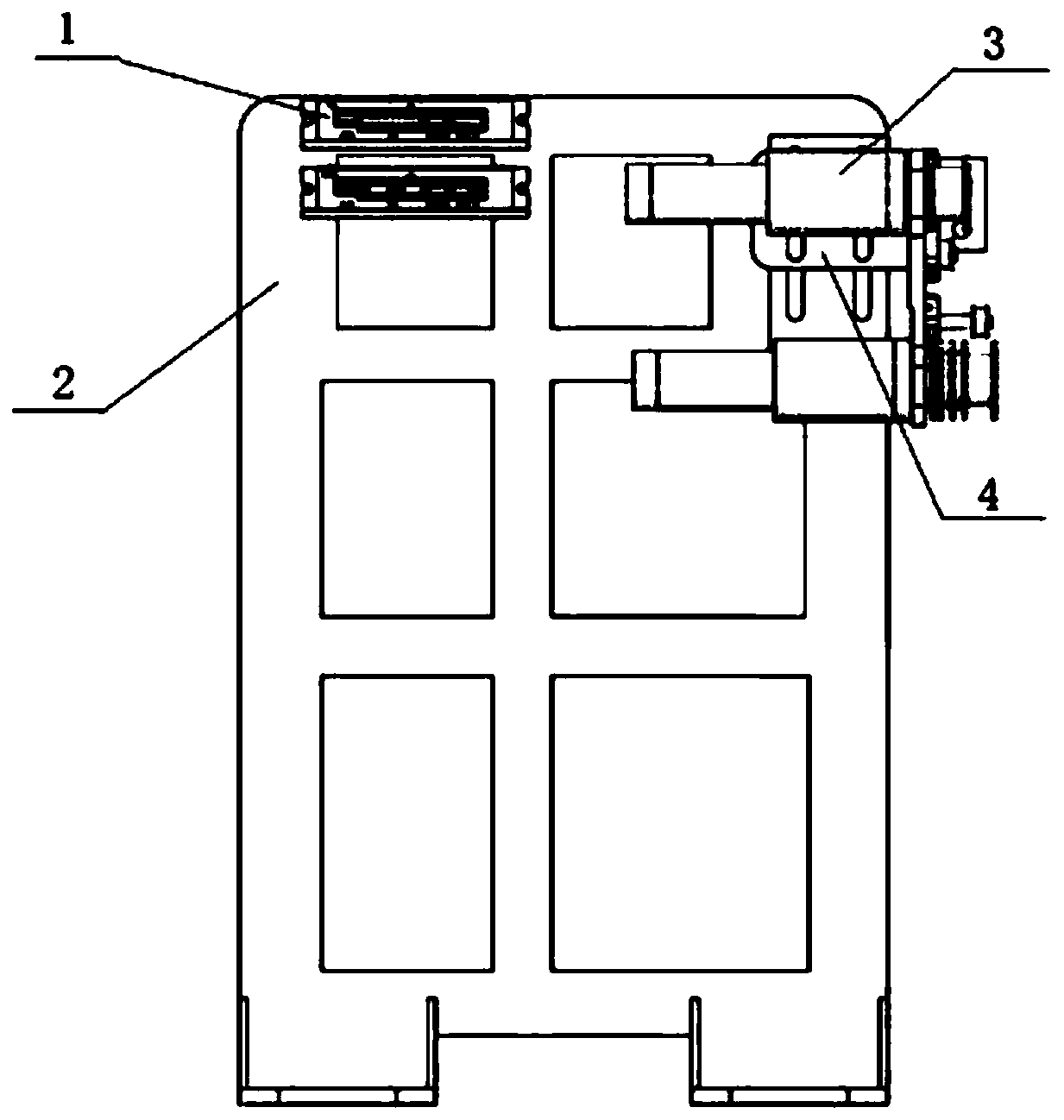
[0023] Specific implementation mode two: combination Figure 1-Figure 4 Describe this embodiment, a flexible rope-driven elbow-joint exoskeleton robot with a compensation device described in this embodiment, the drive device I includes a motor driver 1, a backplane connector 4, a first motor output wheel 5, and a second motor output wheel. Wheel 13, Bowden wire fixing blocks of two connectors, two drive motors 3 and four tensioning assemblies; the backplane connector 4 is fixedly installed on one side of the backplane 2, and the two drive motors 3 are fixedly installed on On the backplane connector 4 and the backplane 2, the output end of one drive motor 3 is set with a first motor output wheel 5, and the output end of the other drive motor 3 is set with a second motor output wheel 13. The Bowden line fixing block and two tensioning assemblies are fixedly installed on the backplane connector 4 close to the first motor output wheel 5, and the two tensioning assemblies are locat...
specific Embodiment approach 3
[0024] Specific implementation mode three: combination figure 1 with Figure 4 Describe this embodiment, a flexible rope-driven elbow joint exoskeleton robot with a compensating device in this embodiment, each tensioning assembly includes a pretensioning wheel fixing seat 6, a fine-tuning screw 7, a pretensioning slider 8, a first Pretension wheel bearing 9, pretension pulley 10, second pretension wheel bearing 11 and pretension wheel bearing sleeve 12, one end of pretension slider 8 is fixedly installed on pretension wheel holder 6 through fine-tuning screw 7, pretension wheel The tensioner fixing seat 6 is fixedly installed on the backplane connector 4, the first pretensioner bearing 9 and the second pretensioner bearing 11 are set on the other end of the pretensioner slider 8, and the pretensioner pulley 10 is set on the first On the preload wheel bearing 9 and the second preload wheel bearing 11, the preload wheel bearing sleeve 12 is installed on the preload slider 8 nea...
PUM
 Abstract
Description
Claims
Application Information
 - R&D
- Intellectual Property
- Life Sciences
- Materials
- Tech Scout
- Unparalleled Data Quality
- Higher Quality Content
- 60% Fewer Hallucinations
Browse by: Latest US Patents, China's latest patents, Technical Efficacy Thesaurus, Application Domain, Technology Topic, Popular Technical Reports.
© 2025 PatSnap. All rights reserved.Legal|Privacy policy|Modern Slavery Act Transparency Statement|Sitemap|About US| Contact US: help@patsnap.com


