
A Fastener Drilling Auxiliary Equipment Guaranteeing Concentric Precision

A technology of auxiliary equipment and fasteners, applied in drilling/drilling equipment, metal processing equipment, components of boring machines/drilling machines, etc., can solve the problem of insufficient drilling accuracy, adverse effects of aircraft stability, and shaking of drill bits and reamers and other problems, to achieve the effect of a wide range of use

Active Publication Date: 2021-10-22
JIANGSU MINGLUSINLESS STEEL
View PDF0 Cites 0 Cited by
  • Summary
  • Abstract
  • Description
  • Claims
  • Application Information

AI Technical Summary

Problems solved by technology

[0003] During the drilling process, due to the influence of factors such as deep drilling, long drill pipe and reamer anchor rod, the drill bit and reamer are prone to shaking, which affects the machining accuracy of the hole. In addition, there are a large number of fasteners, and there are The possibility of insufficient drilling accuracy is high, and the accumulation of small amounts will have an adverse effect on the stability of the overall structure of the aircraft. The current drilling work has basically realized mechanical automation operations. For special holes on some irregular workpieces The position is still manual drilling, but the drilling machine only strengthens the stability of the drill pipe and the installation of the machine, and does not solve the eccentricity problem of the long drill pipe during high-speed rotation. Manual drilling has high technical requirements for workers, and there is no good concentric positioning auxiliary equipment, and the problem of drilling eccentricity will also occur, resulting in a decrease in drilling accuracy

Method used


Image

  • A Fastener Drilling Auxiliary Equipment Guaranteeing Concentric Precision
  • A Fastener Drilling Auxiliary Equipment Guaranteeing Concentric Precision
  • A Fastener Drilling Auxiliary Equipment Guaranteeing Concentric Precision

Examples


Embodiment Construction

[0024] The following will clearly and completely describe the technical solutions in the embodiments of the present invention with reference to the accompanying drawings in the embodiments of the present invention. Obviously, the described embodiments are only some, not all, embodiments of the present invention. Based on the embodiments of the present invention, all other embodiments obtained by persons of ordinary skill in the art without making creative efforts belong to the protection scope of the present invention.

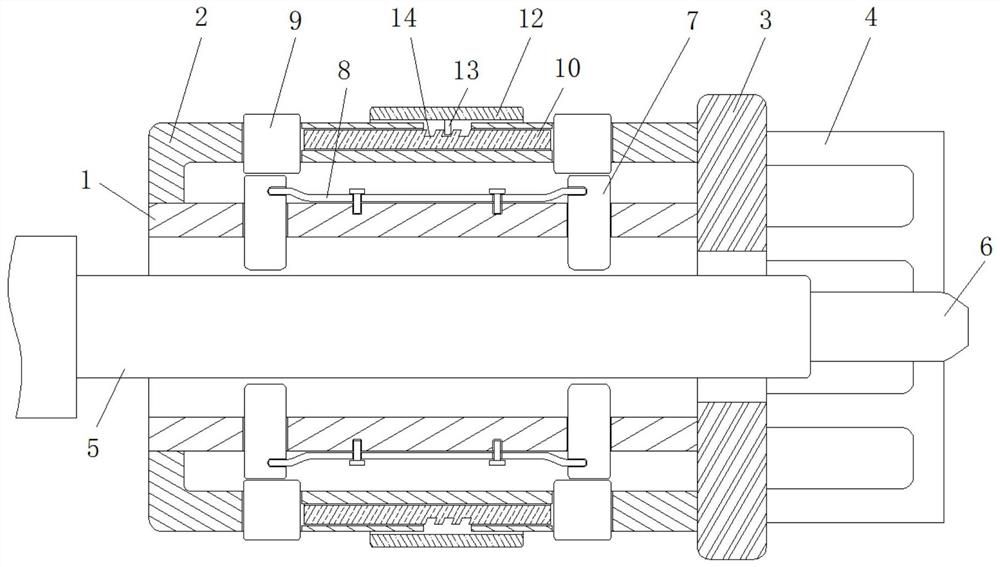
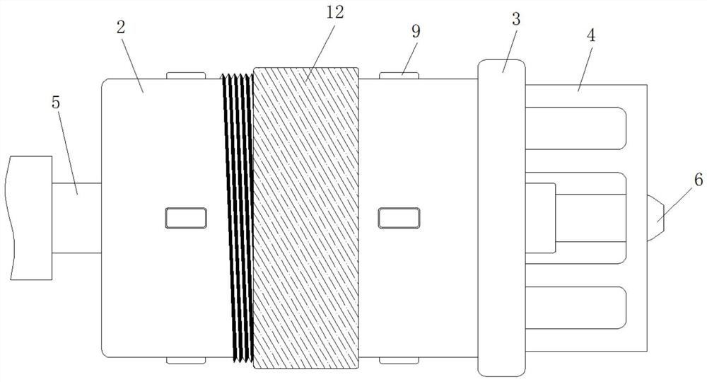
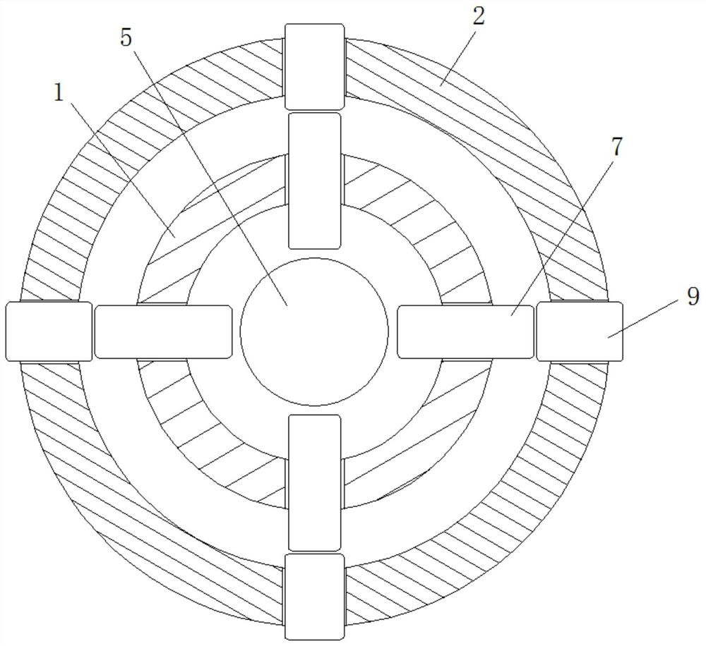
[0025] see Figure 1-7 , a fastener drilling auxiliary device that ensures concentric precision, including an inner cylinder 1, an outer cylinder 2 is fixedly sleeved on the outer side of the inner cylinder 1, and a connecting plate is fixedly connected between the right sides of the inner cylinder 1 and the outer cylinder 2 3. The right side of the connecting plate 3 is fixedly connected with the support ring 4, and the drill pipe 5 is movably inserted on the...


PUM


Abstract

The invention relates to the technical field of drilling auxiliary equipment, and discloses a fastener drilling auxiliary equipment that ensures concentric precision, including an inner cylinder, an outer cylinder is fixedly sleeved on the outer side of the inner cylinder, and the cylinder of the inner cylinder Claws are movably inserted on the wall, elastic plates are fixedly connected to the outer side of the inner cylinder, positioning blocks are movably inserted on the wall of the outer cylinder, and a swivel is inserted in the inner rotation of the outer cylinder, and the outer cylinder The outer side of the cylinder and the outer side of the swivel ring are threadedly sleeved with a sleeve. Set two sets of jaws to hold the drill pipe, so that the drill pipe is always on the axis of the inner cylinder, and the jaws will have a slight displacement when being pushed by the drill pipe, avoiding a large eccentricity of the drill pipe , to control the drilling accuracy, the expansion and contraction of the positioning block can be adjusted by rotating the casing, and then the maximum eccentricity of the drill pipe can be adjusted. It can adapt to various sizes of drill pipes and drilling work with different precision requirements, and has a wide range of applications.

Description

technical field [0001] The invention relates to the technical field of drilling auxiliary equipment, in particular to an auxiliary drilling equipment for fasteners that ensures concentric precision. Background technique [0002] There are about several million fasteners on the aircraft, which ensures the stability and connection of the aircraft. The processing of the fastener holes on the aircraft is generally drilling, which is suitable for the through holes for mounting screws and some rivet mounting holes, and some holes It is a counterbore and a stepped hole. Since the counterbore and the stepped hole need to use drills of different sizes during processing, after the drill is replaced, it must be repositioned to align the drill with the original axis. Some aircraft fasteners The high-strength bolts are installed with a tight fit, and reaming is required after drilling, and the concentric positioning accuracy of the reamer and the drilling is required to be very high. ...

Claims


Application Information

Patent Timeline
Patent Type & Authority Patents(China)
IPC IPC(8): B23Q3/00B23B47/00
CPCB23B47/00B23Q3/00
Inventor 梁育娟
Owner JIANGSU MINGLUSINLESS STEEL
Learn More