
Optical fiber connector and optical fiber contact

An optical fiber connector and connector technology, which is applied to optical components, light guides, optics, etc., can solve the problems of poor connection stability between MT pins and connector shells, and achieve poor connection stability, improve sealing performance, and improve connection. The effect of stability

Inactive Publication Date: 2020-05-22
CHINA AVIATION OPTICAL-ELECTRICAL TECH CO LTD
View PDF7 Cites 0 Cited by
  • Summary
  • Abstract
  • Description
  • Claims
  • Application Information

AI Technical Summary

Problems solved by technology

[0005] The purpose of the present invention is to provide a fiber optic connector to solve the problem of poor connection stability between the MT ferrule of the current fiber optic connector and the connector housing; in addition, the purpose of the present invention is to provide a fiber optic connector used Fiber Optic Contacts

Method used

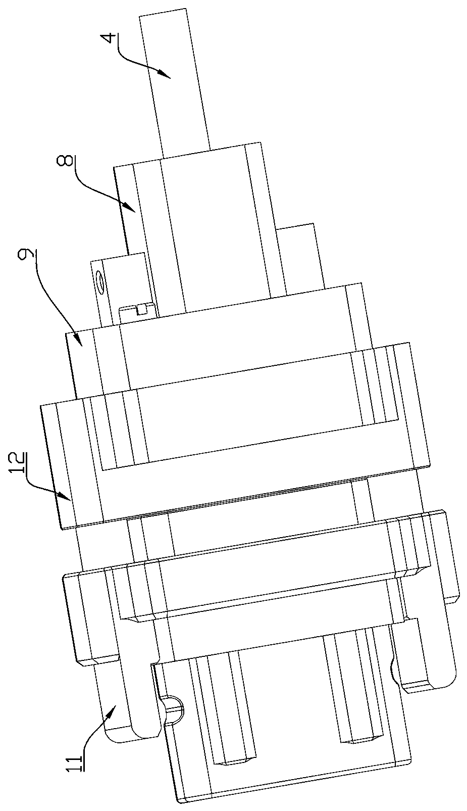
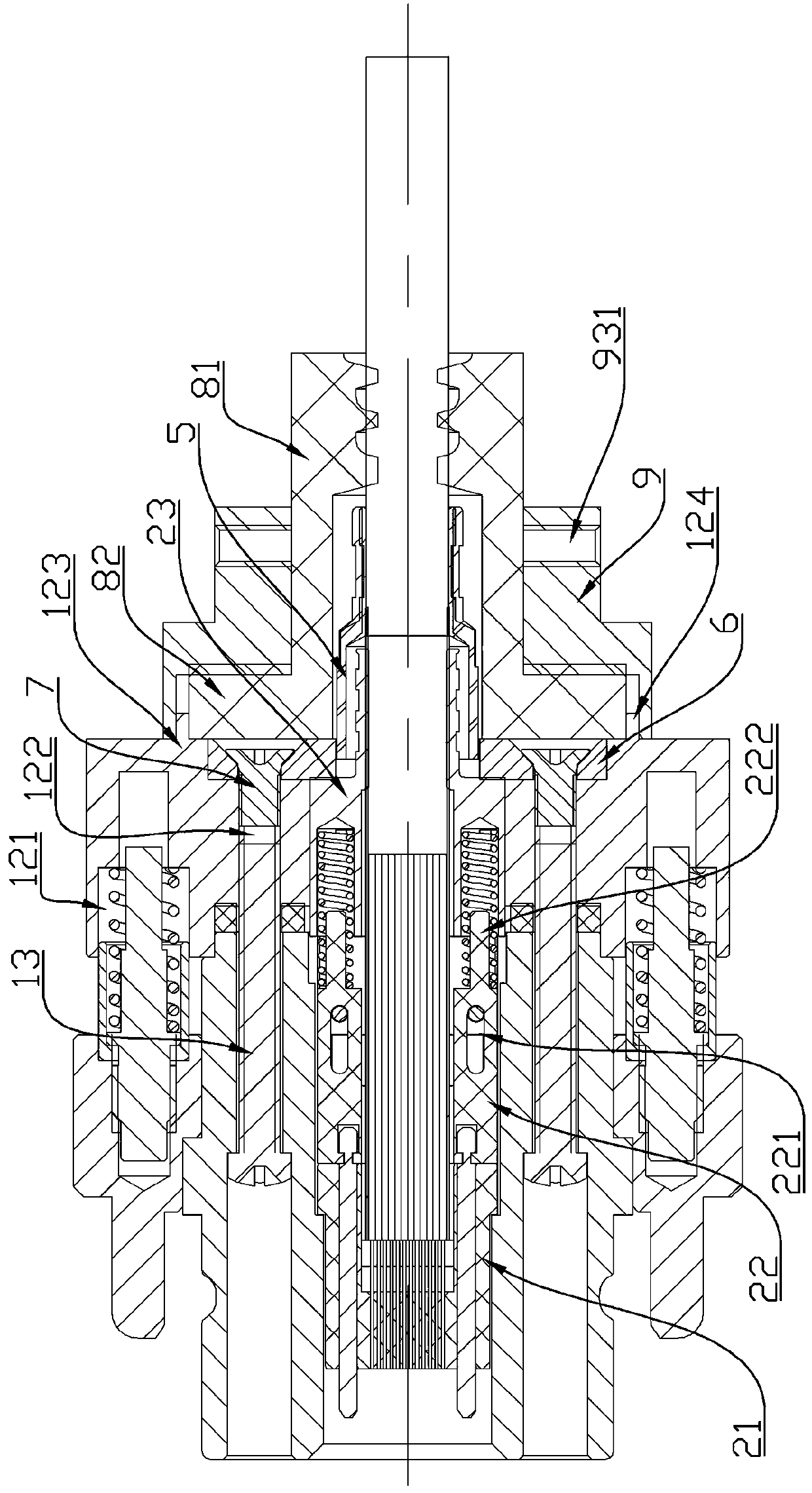
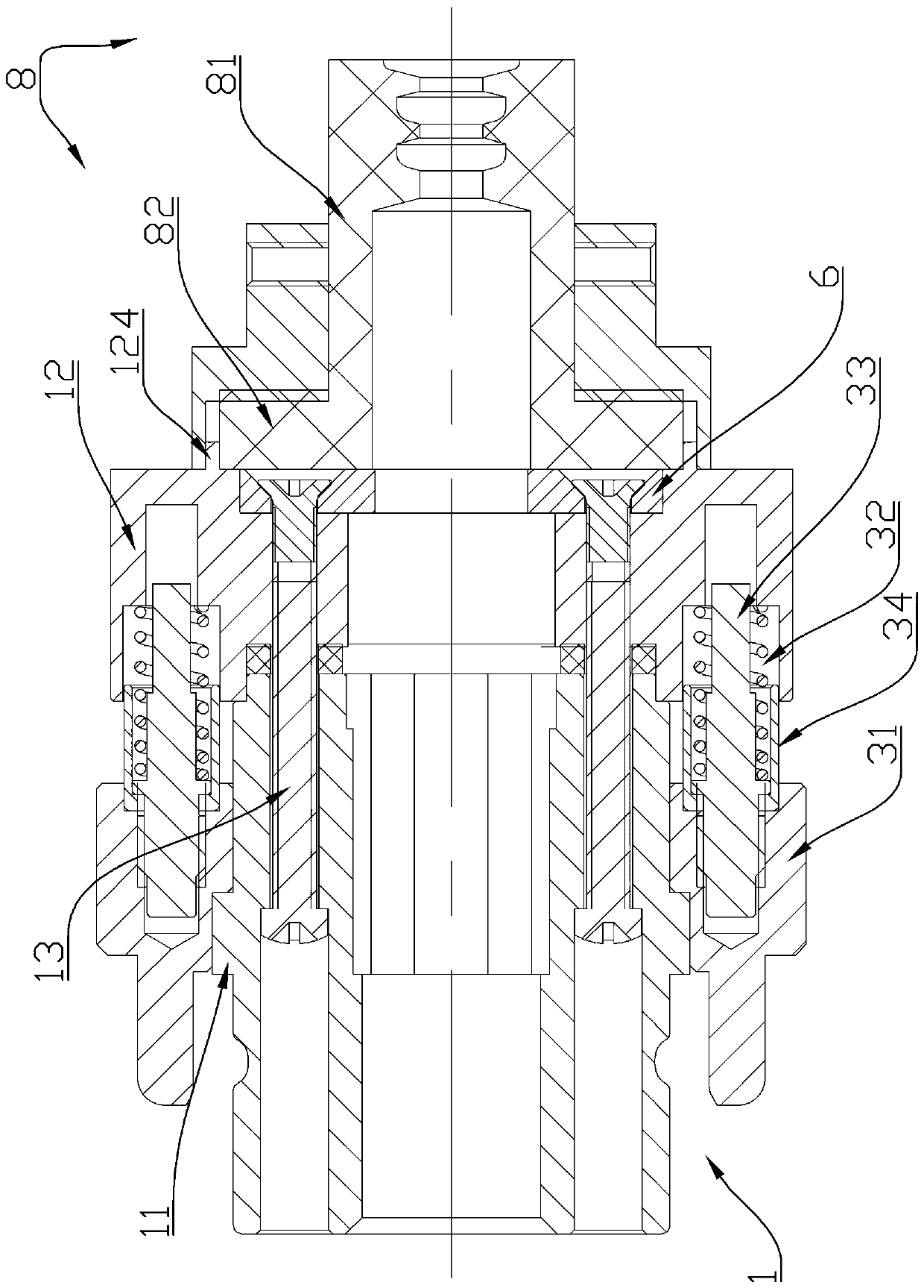

Image

  • Optical fiber connector and optical fiber contact
  • Optical fiber connector and optical fiber contact
  • Optical fiber connector and optical fiber contact

Examples


Embodiment Construction

[0049]In order to make the object, technical solution and advantages of the present invention clearer, the present invention will be further described in detail below in conjunction with the accompanying drawings and embodiments. It should be understood that the specific embodiments described here are only used to explain the present invention, and are not intended to limit the present invention, that is, the described embodiments are only some of the embodiments of the present invention, but not all of the embodiments. The components of the embodiments of the invention generally described and illustrated in the figures herein may be arranged and designed in a variety of different configurations.

[0050] Accordingly, the following detailed description of the embodiments of the invention provided in the accompanying drawings is not intended to limit the scope of the claimed invention, but merely represents selected embodiments of the invention. Based on the embodiments of the ...


PUM


Abstract

The invention relates to an optical fiber connector and an optical fiber contact. The front end of the optical fiber connector is a plugging end, the optical fiber connector comprises a connector shell, a pressing plate, an MT pin, a fixing sleeve and a pushing spring, and the pushing spring is arranged between the fixing sleeve and the MT pin; the pressing plate is fixedly connected to the rear end face of the connector shell and is matched with the rear end of the fixing sleeve in an abutting mode to limit the MT contact pin from being disengaged from the connector shell. According to the optical fiber connector, the MT contact pin is prevented from being separated from the connector shell through the pressing fit of the pressing plate and the rear end of the rear sleeve and the pressingplate is fixed on the rear end surface of the connector shell through the pressing plate fixing screw so that the connection stability of the MT contact pin is improved, and the problem of poor connection stability of the MT contact pin and the connector shell of the conventional optical fiber connector is solved.

Description

technical field [0001] The invention relates to an optical fiber connector and an optical fiber contact piece. Background technique [0002] Since the MT ferrule has a flat structure of 6.4mm×2.5mm, and the optical fiber mounting holes on the MT ferrule are lined up, the MT ferrule is more suitable for ribbon-shaped optical fibers, so MT fiber optic connectors or contacts are generally Fitted with ribbon fiber outlet. [0003] The commonly used size for connecting ribbon fiber to the tail of MT fiber optic contact is 0.4mm×3.4mm. Ribbon fiber has no corresponding strengthening material and has low strength. It is generally used in junction boxes, circuit boards and other parts with protective measures. Separate cabling in racks, cabinets, etc. In some high-density fiber optic connectors, in order to ensure that more fibers are installed in a fiber optic connector, MT fiber optic contacts are often used, but the use of ribbon fibers at the tail of MT fiber optic contacts wi...

Claims


Application Information

Patent Timeline
Patent Type & Authority Applications(China)
IPC IPC(8): G02B6/38
CPCG02B6/3821G02B6/3869G02B6/3887
Inventor 方尚杰
Owner CHINA AVIATION OPTICAL-ELECTRICAL TECH CO LTD
Learn More