Linkage device for promoting limb rehabilitation

A technology of linkage devices and limbs, applied in passive exercise equipment, physical therapy, etc., can solve problems such as unsafe comfort, motor overheating, and injury to users, and achieve the effect of improving comfort

Pending Publication Date: 2020-05-26
南京市江宁医院
0 Cites 0 Cited by

AI-Extracted Technical Summary

Problems solved by technology

[0002] Patients after stroke mainly rely on passive muscle training. The linkage system in the prior art has the following disadvantages: 1. It is not safe and comfortable, and it is easy to hurt the user; 2. It does not have a temperature adjustme...

Method used

During use, the sleeve 6 is set on the arm/leg, pulls the pulling member 30 on the first liquid bag 7 and the second liquid bag 8, so that the first liquid bag 7 is positioned at the elbow joint/knee joint, The second liquid bag 8 is located at the wrist joint/ankle joint, the valve body 5 is opened, and the pump body 3 draws the liquid in the water tank 10 into the first liquid bag 7 and the second liquid bag 8, and the first liquid bag 7 and the second liquid bag 8 are controlled by the pressure sensor 9...

Abstract

The invention discloses a linkage device for promoting limb rehabilitation. The linkage device comprises a shell, a control piece, a water tank and a pump body are arranged in the shell, the water outlet pipe of the pump body communicates with a three-way piece, the outlet of the three-way piece is provided with a first communicating pipe and a second communicating pipe, valve bodies are arrangedon the first communicating pipe and the second communicating pipe, one end of the first communicating pipe is communicated with the three-way piece, a first liquid bag is arranged at the other end ofthe first communicating pipe, one end of the second communicating pipe is communicated with the three-way piece, a second liquid bag is arranged at the other end of the second communicating pipe, thelinkage device comprises an oversleeve, and pressure sensors are arranged on the first liquid bag and the second liquid bag. According to the linkage device, the arm/leg is sleeved with the oversleeve, pulling pieces on the first liquid bag and the second liquid bag are pulled to make the first liquid bag located at the elbow joint/knee joint, so stretching of the arm/leg and intermittent rotationof the pump body are achieved, reciprocating motion of the arm/leg is achieved, and the purpose of exercising is achieved.

Application Domain

Chiropractic devices

Technology Topic

Elbow jointsRehabilitation +5

Image

  • Linkage device for promoting limb rehabilitation
  • Linkage device for promoting limb rehabilitation
  • Linkage device for promoting limb rehabilitation

Examples

  • Experimental program(1)

Example Embodiment

[0021] The technical solutions in the embodiments of the present invention will be clearly and completely described below with reference to the accompanying drawings in the embodiments of the present invention. Obviously, the described embodiments are only a part of the embodiments of the present invention, but not all of the embodiments. Based on the embodiments of the present invention, all other embodiments obtained by those of ordinary skill in the art without creative efforts shall fall within the protection scope of the present invention.
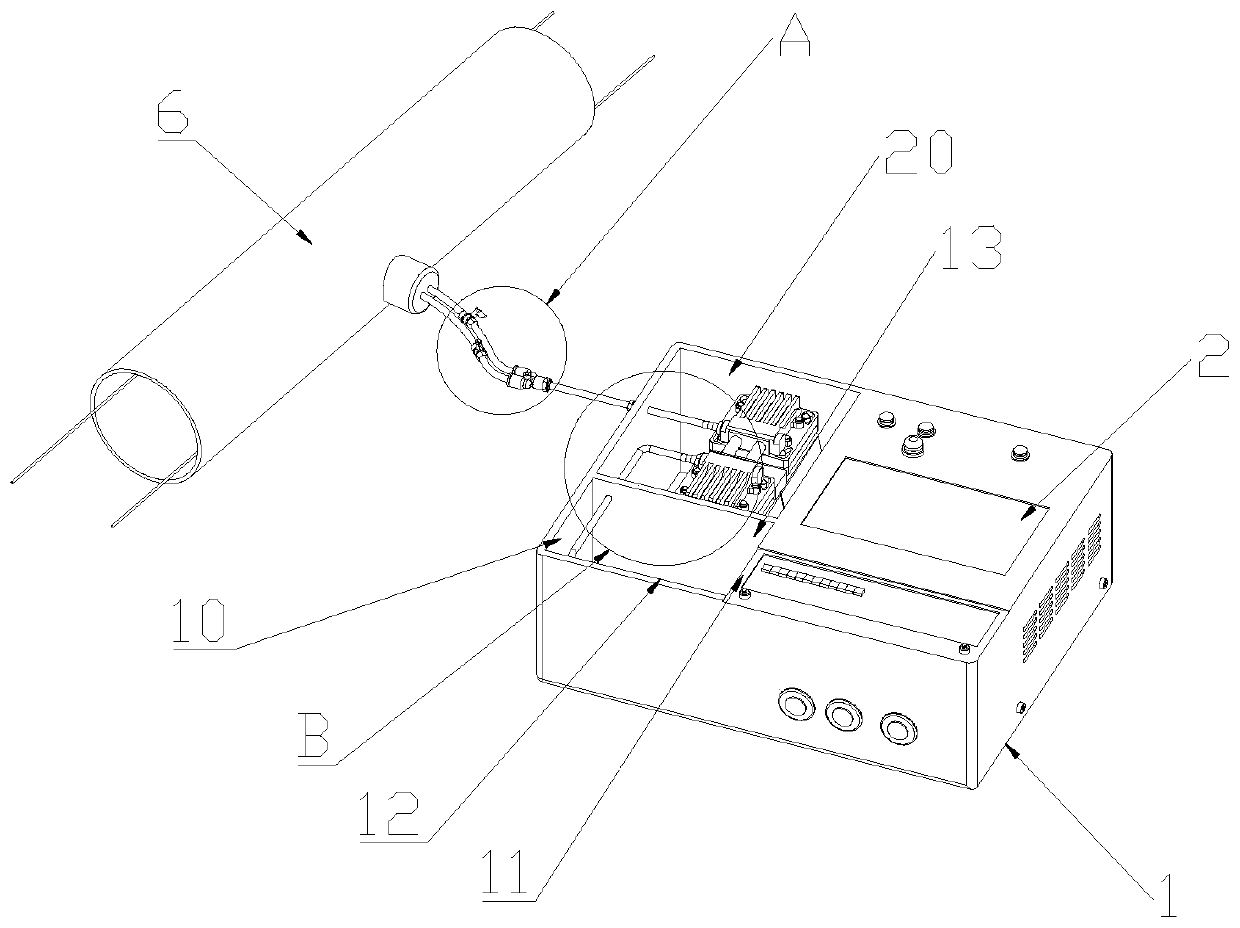
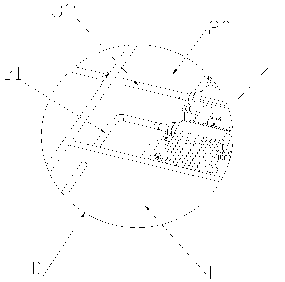
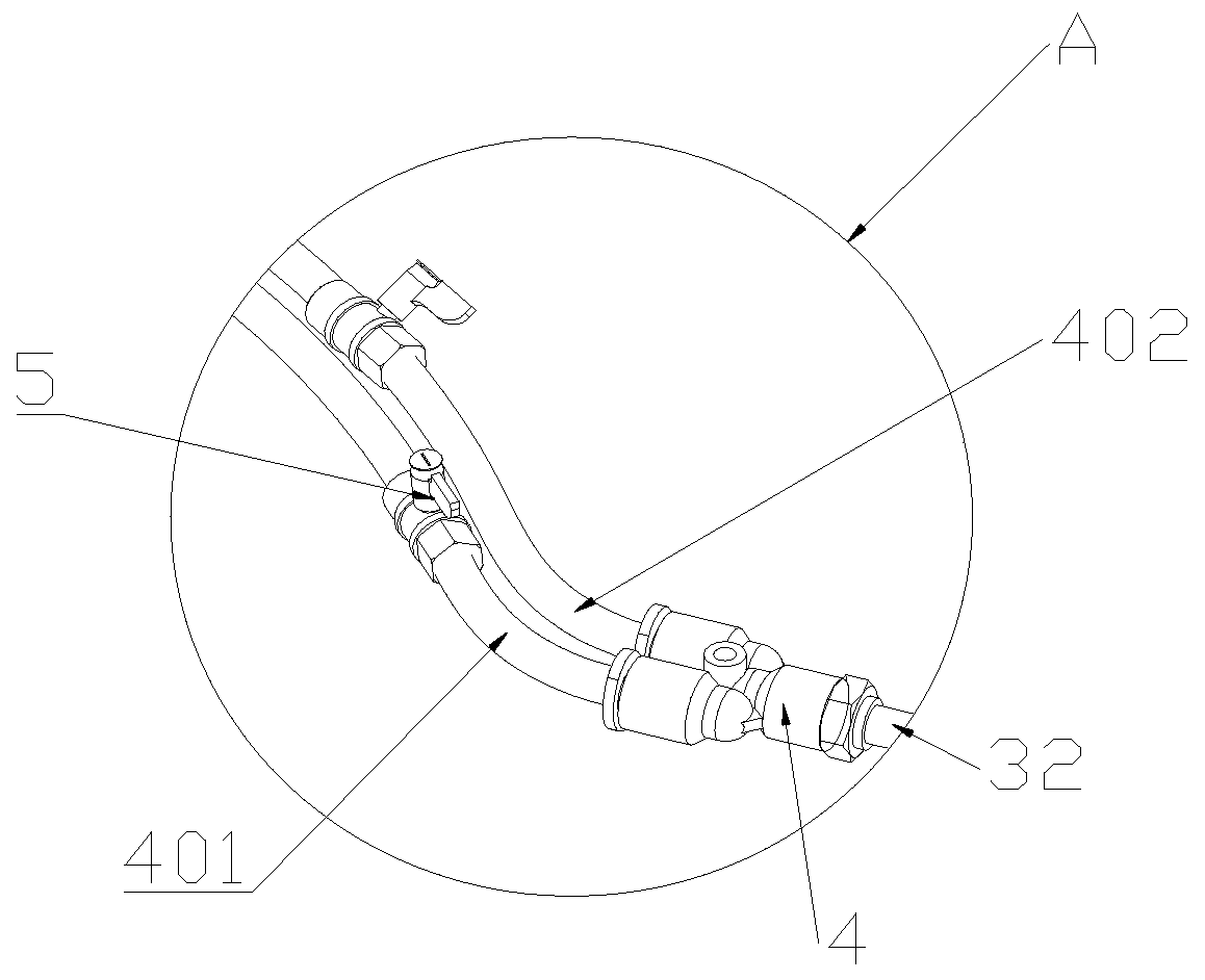
[0022] A linkage device for promoting limb rehabilitation, the linkage device comprises a housing 1, such as figure 1 As shown, the housing 1 is provided with a control part 2, a water tank 10 and a pump body 3, the pump body 3 is electrically connected with the control part 2, the water inlet pipe 31 of the pump body 3 is connected with the water tank 10, and the water outlet pipe 32 of the pump body 3 A tee 4 is communicated with, and the outlet of the tee 4 is provided with a first communication pipe 401 and a second communication pipe 402, such as image 3 As shown, the first communication pipe 401 and the second communication pipe 402 are both provided with a valve body 5, one end of the first communication pipe 401 is communicated with the tee 4, the other end is provided with a first liquid bladder 7, and the second communication pipe One end of the 402 is communicated with the tee 4, and the other end is provided with a second liquid bladder 8, such as Figure 4 As shown, the linkage device includes a sleeve 6, the first liquid bag 7 and the second liquid bag 8 are both located in the sleeve sleeve 6, the first liquid bag 7 and the second liquid bag 8 are provided with pressure sensors 9, and the pressure sensing The device 9 is electrically connected to the control element 2 .
[0023] The casing 1 is provided with a first partition 11 , the control member 2 is located on one side of the first partition 11 , and a groove 12 is formed on the other side. The groove 12 is provided with a second partition 13 , and the second partition 13 Divide the tank body 12 into a water tank 10 and a placement tank 20, such as figure 2 As shown, the pump body 3 is located in the placement tank 20 , and the pump body 3 communicates with the water tank 10 through the water inlet pipe 31 through the second partition 13 , and the bottom of the water tank 10 is provided with a heating device.
[0024] Both ends of the first liquid bag 7 and the second liquid bag 8 are provided with a pulling member 30 , and the pulling member 30 extends out of the sleeve 6 for position adjustment of the first liquid bag 7 and the second liquid bag 8 .
[0025] One end of the water outlet pipe 32 is communicated with the pump body 3 , and the other end is communicated with the tee 4 , and the tee 4 is communicated with the water outlet pipe 32 , the first communication pipe 401 and the second communication pipe 402 respectively.
[0026] When in use, put the sleeve 6 on the arm/leg, pull the pulling member 30 on the first fluid bag 7 and the second fluid bag 8, so that the first fluid bag 7 is located at the elbow/knee joint, and the second fluid bag 7 is located at the elbow/knee joint. The sac 8 is located at the wrist/ankle joint, the valve body 5 is opened, the liquid in the water tank 10 is pumped into the first sac 7 and the second sac 8 through the pump body 3, and the first sac 7 is controlled by the pressure sensor 9 And the pressure of the second liquid bladder 8 on the human body, so that the elbow joint/knee joint and the wrist joint/ankle joint are opened to realize the straightening of the arm/leg, and the pump body 3 rotates intermittently to realize the reciprocating motion of the arm/leg. To achieve the purpose of exercise, the bottom of the water tank 10 is provided with a heating device to heat the liquid in the water tank 10, adjust the water temperature, and improve the comfort of the user.
[0027] In the description of this specification, description with reference to the terms "one embodiment," "example," "specific example," etc. means that a particular feature, structure, material, or characteristic described in connection with the embodiment or example is included in at least one aspect of the present invention. in one embodiment or example. In this specification, schematic representations of the above terms do not necessarily refer to the same embodiment or example. Furthermore, the particular features, structures, materials or characteristics described may be combined in any suitable manner in any one or more embodiments or examples.
[0028] The foregoing has shown and described the basic principles, main features and advantages of the present invention. Those skilled in the art should understand that the present invention is not limited by the above-mentioned embodiments, and the descriptions in the above-mentioned embodiments and the description are only to illustrate the principle of the present invention. Without departing from the spirit and scope of the present invention, the present invention will have Various changes and modifications fall within the scope of the claimed invention.

PUM

no PUM

Description & Claims & Application Information

We can also present the details of the Description, Claims and Application information to help users get a comprehensive understanding of the technical details of the patent, such as background art, summary of invention, brief description of drawings, description of embodiments, and other original content. On the other hand, users can also determine the specific scope of protection of the technology through the list of claims; as well as understand the changes in the life cycle of the technology with the presentation of the patent timeline. Login to view more.

Similar technology patents

Water mixing valve of water heater

Owner:SHANDONG ANALYSIS & TEST CENT

Athletic Protective Mouthpiece and Lip Shield Apparatus

ActiveUS20150209645A1improve comfortimproved channel structure
Owner:ZENTS SHAWN ALAN

Intelligent control method for fresh air handling unit and fresh air handling unit applying method

ActiveCN106196505AGuarantee the quality of air environmentImprove comfort
Owner:北京同衡能源环境科学研究院有限公司

LED lighting control device

InactiveCN101959347AImprove power conversion efficiencyImprove comfort
Owner:HUAZHONG UNIV OF SCI & TECH

Classification and recommendation of technical efficacy words

  • Improve comfort

Fan

ActiveUS20100150699A1improve comfortlow turbulence
Owner:UNIVERSAL SAFETY RESPONSE +1

Intelligent adjustment system of indoor air conditioner and adjustment method of same

ActiveCN104896668AEasy control processImprove comfort
Owner:GD MIDEA HEATING & VENTILATING EQUIP CO LTD +1

Contact Lens Package Solution

InactiveUS20080307751A1improve comfort
Owner:MENICON SINGAPORE PTE LTD

Coffee cup lid

InactiveUS20090294460A1improve comfortreduce spill
Owner:COMERICA BANK

Anti-shock damping safety seat

Owner:CHONGQING TECH & BUSINESS INST
Why Eureka
Try Eureka