A percussion device for microseismic positioning and correction in deep rock mass
What is AI technical title?
AI technical title is built by Patsnap AI team. It summarizes the technical point description of the patent document.
A positioning correction, deep-seated technology, applied in measuring devices, using sonic/ultrasonic/infrasonic waves to analyze solids, instruments, etc. Inexpensive and easy to operate
Active Publication Date: 2021-06-18
DALIAN UNIV OF TECH
View PDF15 Cites 0 Cited by
Summary
Abstract
Description
Claims
Application Information
AI Technical Summary
This helps you quickly interpret patents by identifying the three key elements:
Problems solved by technology
Method used
Benefits of technology
Problems solved by technology
For example, the wave speed and the absolute time of wave arrival at the sensor are not accurate enough, which will affect the seismic phase analysis and determine the location of the seismic source, so it is necessary to use the monitoring system to perform pre-calibration of the positioning system
Regarding the positioning problem, the positioning correction in the early stage of microseismic monitoring usually produces shock waves when the staff hit the ground surface during the positioning correction, and the source position is calculated by receiving the signal from the sensor. On the one hand, due to the different and slow response speed of the staff, the calculated wave On the other hand, the cracks generated by the surface excavation disturbance will seriously affect the normal propagation of the shock wave, and the mine shock wave from the source propagates in all directions, and the direction of the shock wave generated by the surface percussion is only below the ground. , which is inconsistent with the shock wave generated by the actual microseismic
Method used
Image
Click on the blue label to locate the original text in one second.
Reading with bidirectional positioning of images and text.
Examples
Embodiment 1
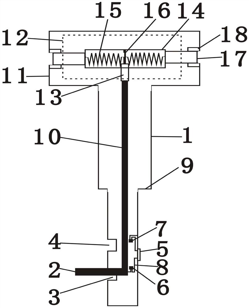
[0020] A percussion device for positioning and correcting microseismic deep rock mass, comprising: a main body system, a control system, an elastic system, a timing system, and a percussion system, and the control system, the elastic system, the timing system, and the percussion system are all installed on the On the main body system, the control system is respectively connected with the elastic system and the timing system, the control system is used to simultaneously trigger the elastic system and the timing system, and the knocking system is connected with the elastic system.
[0021] The main system includes: a shell 1, a bayonet A3, a bayonet B4, an expansion joint 9, an impact chamber 11, and an upper cover 12. The shell 1 is provided with the bayonet A3 and the bayonet B4, and the shell 1 is An adjustable length telescopic joint 9 is provided, the impact chamber 11 is connected with the casing 1 , the upper cover 12 is arranged on the impact chamber 11 , and a scale mark...
Embodiment 2
[0031] The invention develops a portable, easy-to-operate and low-cost percussion device for deep rocks.
[0032] The device includes a main body system, a control system, an elastic system, a timing system and a knocking system. It is suitable for avoiding the correction of the positioning system in the early stage of microseismic monitoring due to the cracks generated by the disturbance of surface excavation.
[0033] (1) Main system
[0034] The main system is mainly composed of shell 1, bayonet A3, bayonet B4, expansion joint 9, impact chamber 11, and upper cover 12.
[0035] (2) Control system.
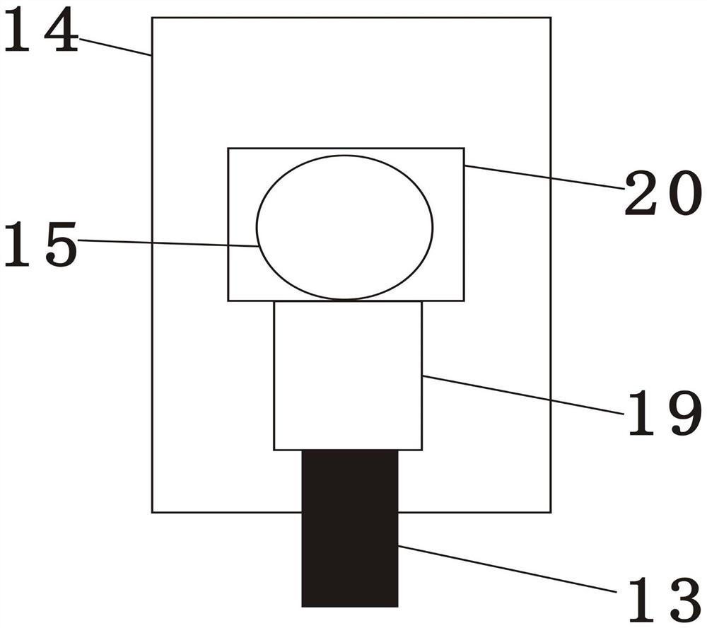
[0036] Control system is mainly made up of control handle 2, control rod 10, control button 13, push rod 19, baffle plate 20.
[0037] (3) elastic system
[0038] The elastic force system is mainly made up of spring chamber 14, spring 15, fixed plate 16.
[0039] (4) Timing system
[0040] The timing system is mainly composed of a timer 5, a positive plate 6, a negative plate...
PUM
Abstract
The utility model relates to a percussion device for microseismic positioning and correction in the deep part of a rock mass, which belongs to the technical field of rock mass engineering. Technical points: including: main body system, control system, elastic system, timing system, and percussion system. The control system, elastic system, timing system, and percussion system are all installed on the main body system. The elastic system is connected to the timing system, the control system is used to simultaneously trigger the elastic system and the timing system, and the knocking system is connected to the elastic system. Beneficial effects: the percussion device for microseismic positioning and correction in the deep part of the rock mass according to the present invention can prevent the cracks generated by the surface excavation disturbance from affecting the accuracy of the pre-calibration positioning system for microseismic monitoring; the depth of insertion into the rock mass can be controlled, and the percussion can be controlled The strength; knocking and timing occur at the same time, eliminating human error; easy to carry, easy to operate, and low in price.
Description
technical field [0001] The invention belongs to the technical field of rock mass engineering, including mining, water conservancy and hydropower, transportation, etc., and in particular relates to a correction and positioning device for deep microseismic monitoring of rock mass. Background technique [0002] The control of deep high-stress surrounding rock needs to be based on the evaluation of deformation, damage and failure state of surrounding rock under high-stress conditions. However, due to the particularity of rock materials (existence of joints, fissures, etc.) and the complexity of geological conditions, it is difficult to use a single monitoring method to evaluate the fracture damage state of rock mass during on-site construction. Although rock mass stability monitoring methods such as stress gauges and displacement meters can measure stress and deformation at local points, they cannot grasp the global state changes of deep mining rock mass and the factors caused b...
Claims
Application Information
Patent Timeline
Application Date:The date an application was filed.
Publication Date:The date a patent or application was officially published.
First Publication Date:The earliest publication date of a patent with the same application number.
Issue Date:Publication date of the patent grant document.
PCT Entry Date:The Entry date of PCT National Phase.
Estimated Expiry Date:The statutory expiry date of a patent right according to the Patent Law, and it is the longest term of protection that the patent right can achieve without the termination of the patent right due to other reasons(Term extension factor has been taken into account ).
Invalid Date:Actual expiry date is based on effective date or publication date of legal transaction data of invalid patent.

