Dust removing equipment for LED lamp

A technology of LED lamps and dust removal equipment, which is applied in the direction of smoke and dust removal, cleaning methods and utensils, and cleaning methods using tools. Stable adsorption, improved use effect, and better use effect

Active Publication Date: 2020-06-02
深圳市华冠光电科技有限公司
View PDF6 Cites 5 Cited by
  • Summary
  • Abstract
  • Description
  • Claims
  • Application Information

AI Technical Summary

Problems solved by technology

[0003] At present, the existing dust removal method usually uses a rag to wipe the dust in the lamp. This method is not only extremely inefficient, but also difficult to wipe off the dust in the lamp, and the dust removal effect is very unsatisfactory. It is impossible to remove dust for lamps of different sizes, and there are certain limitations in use. Therefore, it is urgent to design a dust removal device for LED lamps to solve the above problems

Method used


Image

  • Dust removing equipment for LED lamp
  • Dust removing equipment for LED lamp
  • Dust removing equipment for LED lamp

Examples


Embodiment 1

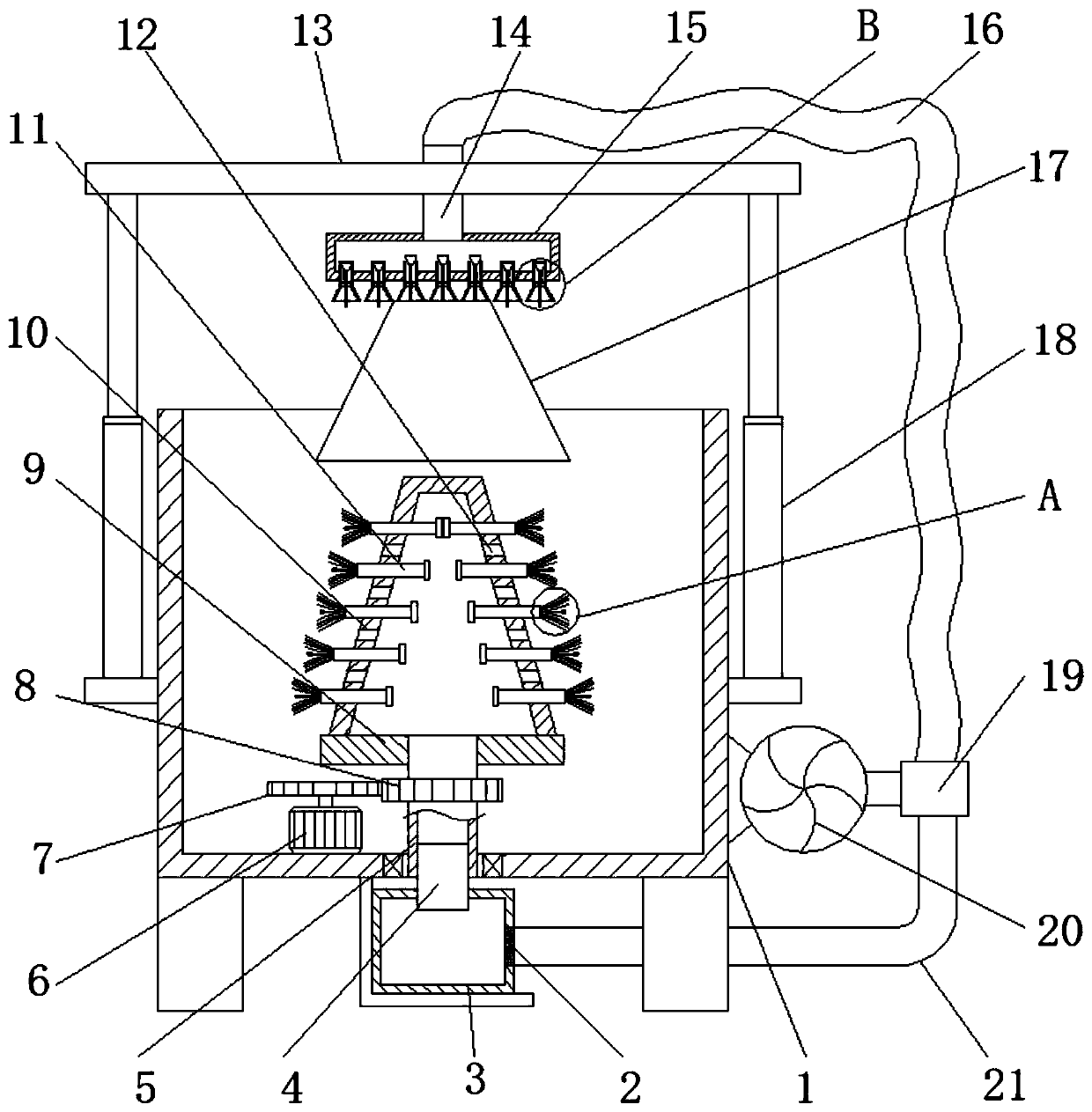
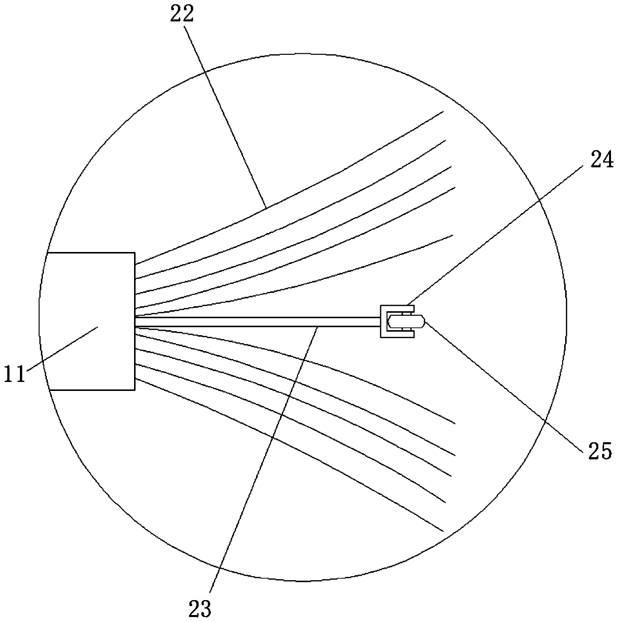
[0031] refer to Figure 1-4 , a kind of dust removal equipment for LED lamps, comprising a dust removal box 1, the bottom inner wall of the dust removal box 1 is provided with a mounting opening, and the inner wall of the installation opening is connected to a rotating tube 5 through bearing rotation, and the outer wall of the rotating tube 5 is welded with a turntable 9, and The top outer wall of the turntable 9 is welded with a fixed cover 10. The cross section of the fixed cover 10 is trapezoidal. Circularly distributed concave holes, and the inner wall of the concave hole is slidingly connected with a sliding rod 11, the outer wall of one end of the sliding rod 11 is welded with a stopper, and the outer wall of the other end of the sliding rod 11 is bonded with a brush 22, the bottom inner wall of the dust removal box 1 A motor 6 is connected by bolts, and one end of the output shaft of the motor 6 is provided with a driving wheel 7, and the outer wall of the rotating tube...

Embodiment 2

[0035] refer to Figure 5 , a dust removal device for LED lamps. Compared with Embodiment 1, this embodiment also includes a ring 33 threaded on the outer wall of the collecting pipe 4 , and a cloth bag 34 bonded to the inner wall of the ring 33 .

[0036] Working principle: when in use, the ring 33 can be set on the collecting pipe 4, and the dust can be collected through the cloth bag 34 on the ring 33, which is more convenient to clean the dust.


PUM


Abstract

The invention discloses dust removing equipment for an LED lamp. The equipment comprises a dust removing box, a mounting opening is formed in the inner wall of the bottom of the dust removing box, a rotating pipe is rotationally connected to the inner wall of the mounting opening through a bearing, a rotating disc is arranged on the outer wall of the rotating pipe, a fixing cover is welded to theouter wall of the top of the rotating disc, the cross section of the fixing cover is trapezoidal, dust collecting holes annularly distributed at equal intervals are formed in the outer wall of the fixing cover, multiple layers of concave holes annularly distributed at equal intervals are formed in the outer wall of the fixing cover, sliding rods are slidably connected to the inner walls of the concave holes, and stopping blocks are welded to the outer walls of one ends of the sliding rods. According to the equipment, dust on the lamp can be rapidly brushed away; rollers can be in contact withthe inner wall of the lamp, so that the phenomenon that brushes are tightly attached to the lamp due to too large centrifugal force and then the dust cannot be completely brushed away is effectively avoided; the rollers are in rotary contact with the lamp, so that the lamp cannot be abraded; and meanwhile, dust can be effectively collected, so that the situation that dust removing is effected dueto the fact that the dust flies everywhere is avoided.

Description

technical field [0001] The invention relates to the technical field of dust removal for lamps, in particular to a dust removal device for LED lamps. Background technique [0002] Lamp refers to a device that can transmit light, distribute and change the light distribution of the light source, so that the light source can emit light reliably to meet the light requirements of human beings when they are engaged in various activities. During the production process, the parts of the lamp are produced Afterwards, it needs to be assembled, and before the assembly, the lamp needs to be dedusted to ensure the cleanliness of the inside of the lamp. [0003] At present, the existing dust removal method usually uses a rag to wipe the dust in the lamp. This method is not only extremely inefficient, but also difficult to wipe off the dust in the lamp, and the dust removal effect is very unsatisfactory. It is impossible to remove dust for lamps of different sizes, and there are certain li...

Claims


Application Information

Patent Timeline
Patent Type & Authority Applications(China)
IPC IPC(8): B08B1/04B08B15/04B08B13/00B01D46/10
CPCB01D46/10B08B1/002B08B1/04B08B13/00B08B15/04
Inventor 袁秋龙
Owner 深圳市华冠光电科技有限公司
Why Eureka
Try Eureka