Leg structure of jumping robot

A robot and leg technology, applied in the field of the leg structure of jumping robots, can solve the problems of poor ability to jump obstacles, the robot does not have the ability to jump obstacles, and increase the safety risk of personnel, so as to achieve the effect of enhancing the ability to jump and jump obstacles.

Active Publication Date: 2020-06-02
HUNAN UNIV OF TECH
View PDF9 Cites 0 Cited by
  • Summary
  • Abstract
  • Description
  • Claims
  • Application Information

AI Technical Summary

Problems solved by technology

[0002] Robots play an important role in many fields. In these fields, robots can replace humans to carry dangerous objects, and can replace humans to work in environments that are not suitable for human activities and survival. However, existing robots do not have the ability to jump obstacles or The ability to jump over obstacles is poor, so there are still some more dangerous tasks that cannot be replaced by robots. They can only be completed by people wearing special equipment, but this increases the safety risk of personnel.

Method used


Image

  • Leg structure of jumping robot
  • Leg structure of jumping robot

Examples


Embodiment 1

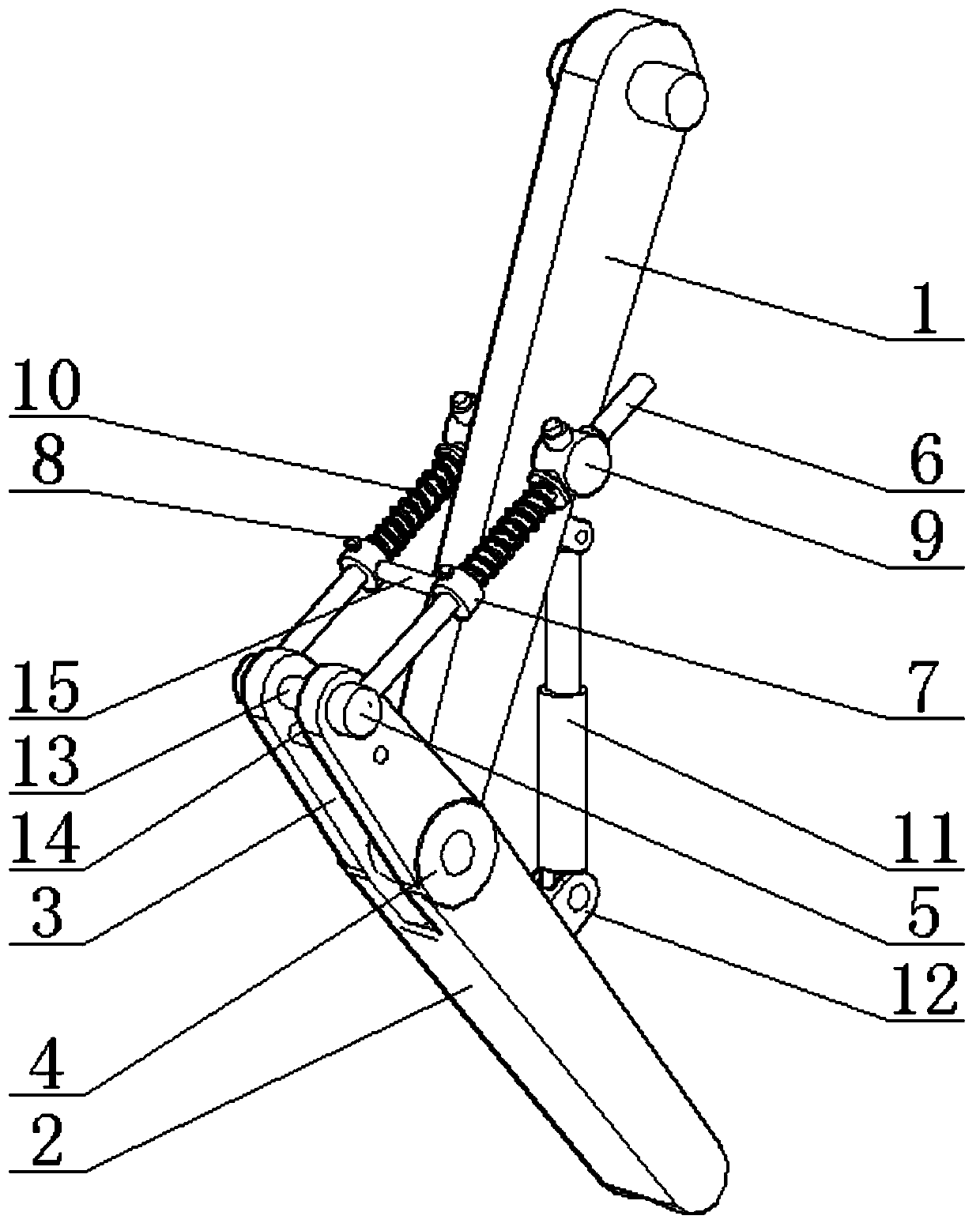
[0017] see Figure 1-2 , a leg structure of a jumping robot, comprising a mechanical thigh 1 and a mechanical lower leg 2, the upper middle part of the mechanical lower leg 2 is provided with a mounting groove 3, the bottom of the mounting groove 3 is provided with a mechanical joint 4, and the mechanical joint 4 moves with the bottom of the mechanical thigh 1 The connection is used for the bending activity between the mechanical thigh 1 and the mechanical lower leg 2. The outer side of the top of the mechanical lower leg 2 is relatively symmetrically installed with a movable block 5. The movable block 5 can be rotated and connected on the mechanical lower leg 2, and the outer surface of the movable block 5 is fixedly connected. There is a movable rod 6, the middle part of the movable rod 6 is socketed and connected with a movable sleeve 7, and the movable sleeve 7 is provided with a screw hole, and the inner thread of the screw hole is connected with a locking bolt 8, which is...

Embodiment 2

[0019] In the present invention, a support rod 13 is fixedly connected between the inner sides of the top ends of the installation grooves 3 , and a plurality of sets of connecting rods 14 are fixedly connected to the inner side of the installation groove 3 on one side of the support rods 13 to ensure the internal stability of the installation groove 3 .

[0020] A fixed rod 15 is detachably connected between the two groups of movable sleeves 7 to ensure the consistency of the positions of the two groups of movable sleeves 7 on the movable rod 6, thereby ensuring that the potential energy of the two groups of tension springs 10 is approximately the same.

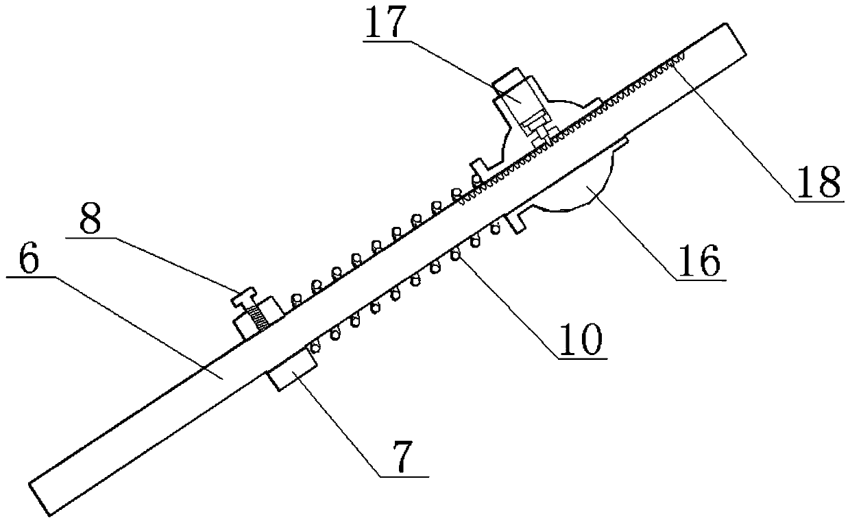
[0021] The self-locking device 9 includes a lock sleeve 16 and an electronic lifting rod 17. A sleeve hole is provided through the middle of the lock sleeve 16, and the movable rod 6 is slidably connected to the inside of the sleeve hole. Rod 17.

[0022] The movable rod 6 located at one end of the self-locking device 9 is p...

Embodiment 3

[0026] The working principle of the present invention is: when working, the electric telescopic rod 11 contracts, making the mechanical thigh 1 and the mechanical lower leg 2 bend and the mechanical thigh 1 and the mechanical lower leg 2 rotate relatively through the mechanical joint 4, and the mechanical thigh 1 and the mechanical lower leg 2 The included angle becomes smaller, and at the same time, the distance between one end of the movable block 5 and the self-locking device 9 increases, thereby increasing the distance between the movable sleeve 7 and the self-locking device 9. After the distance between the two increases, the pulling force The spring 10 is elongated, so that the tension spring 10 stores elastic potential energy. In addition, the movable rod 6 slides in the direction of the movable sleeve 7 in the lock sleeve 16. When the mechanical thigh 1 and the mechanical lower leg 2 bend to the set critical point, the electric telescopic rod 11 stops. shrink, and at th...


PUM


Abstract

The invention discloses a leg structure of a jumping robot. The leg structure comprises a mechanical thigh and a mechanical shank, and a mounting groove is formed in the middle-upper part of the mechanical shank; a mechanical joint is arranged at the bottom of the mounting groove; the mechanical joint is movably connected with the bottom of the mechanical thigh; movable blocks are symmetrically mounted on the outer side of the top end of the mechanical shank; and movable rods are fixedly connected to the outer side faces of the movable blocks. The middles of the movable rods are sleeved with movable sleeves; and the other ends of the movable rods are sleeved with self-locking devices; the self-locking devices are rotationally connected to the two sides of the middle of the mechanical thigh. The movable rods between the movable sleeves and the self-locking devices are connected with a tension spring in a sleeved mode, an electric telescopic rod is arranged between the mechanical thigh and the mechanical shank, hinge pieces are fixedly installed at the two ends of the electric telescopic rod respectively, and the two hinge pieces are fixedly connected to the mechanical thigh and themechanical shank respectively. The leg structure of the jumping robot has the advantages of the simple structure, agreement and strong obstacle jumping capability, and is mainly used for jumping of the robot.

Description

technical field [0001] The invention relates to the technical field of robot structures, in particular to a jumping robot leg structure. Background technique [0002] Robots play an important role in many fields. In these fields, robots can replace humans to carry dangerous objects, and can replace humans to work in environments that are not suitable for human activities and survival. However, existing robots do not have the ability to jump obstacles or The ability to jump over obstacles is poor, so there are still some more dangerous tasks that cannot be replaced by robots. They can only be completed by people wearing special equipment, but this increases the safety risk of personnel. Contents of the invention [0003] Aiming at the above-mentioned deficiencies existing in the prior art, the object of the present invention is to provide a jumping robot leg structure with simple structure, high compactness and strong jumping ability. [0004] The technical solution adopte...

Claims


Application Information

Patent Timeline
Patent Type & Authority Applications(China)
IPC IPC(8): B62D57/032
CPCB62D57/032
Inventor 熊勇刚杨小娟熊眭杨张勇米承继刘水长
Owner HUNAN UNIV OF TECH
Why Eureka
Try Eureka