A middle door guide mechanism of a garbage compactor

A technology of garbage compressor and guide mechanism, which is applied to garbage receptacles, transportation and packaging, etc., can solve the problems of reducing the strength of the box body, damage, deformation of the middle door guide rails and guide grooves, etc., to improve the stability and reliability, Improve the stability and synchronization, the effect of smooth and smooth lifting

Active Publication Date: 2021-08-06
ZHEJIANG HUANLONG MACHINERY CO LTD
View PDF0 Cites 0 Cited by
  • Summary
  • Abstract
  • Description
  • Claims
  • Application Information

AI Technical Summary

Problems solved by technology

In the existing compressed dustbin, steel guide grooves are installed on both sides of the box body and the steel guide rails on both sides of the pull-out middle door cooperate. The middle door is lifted by two sets of hydraulic cylinders. The grooves are matched with steel parts. In order to ensure the stable lifting of the middle door, the hydraulic oil intake must be precisely controlled by the computer to ensure that the lifting force of the two groups of oil cylinders on the middle door is equal; if the hydraulic pressure on the left and right sides of the middle door If the lifting force is not equal, it will cause the middle door guide rail and guide groove to be deformed or even damaged
Due to the use of computer control, the complexity of technology and the cost of production and maintenance are increased
In the prior art, the middle door moving up and down in the garbage compressor is guided by a nylon guide groove structure, but this needs to form a groove on the side plate of the box body, and a nylon guide groove is set in the groove, and the groove structure reduces the The strength of the box is not easy to manufacture, install and maintain

Method used


Image

  • A middle door guide mechanism of a garbage compactor
  • A middle door guide mechanism of a garbage compactor
  • A middle door guide mechanism of a garbage compactor

Examples


Embodiment Construction

[0029] The present invention will be further described below in conjunction with the accompanying drawings.

[0030] This specific embodiment is only an explanation of the present invention, not a limitation of the present invention. Any changes made by those skilled in the art after reading the description of the present invention will be subject to patent law as long as they are within the scope of the claims. protection of.

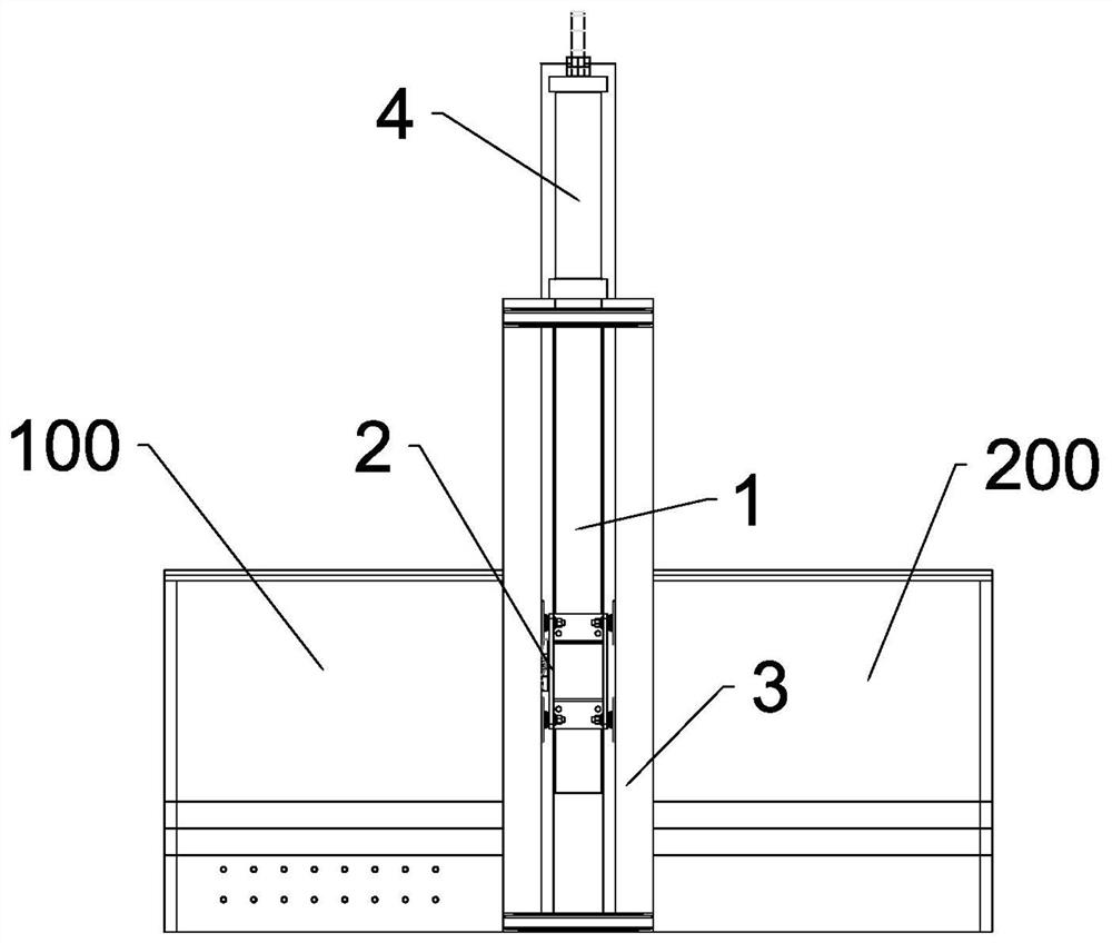
[0031] Such as figure 1 and Figure 4 As shown, a middle door guide mechanism of a garbage compressor includes a middle door 1 , a guide wheel assembly 2 , a guide post 3 , a lifting assembly 4 and a synchronous assembly 5 .

[0032] The middle door 1 is arranged between the front box body 100 and the rear box body 200 of the garbage compressor. The front box 100 is also equipped with a garbage compression system. After the middle door falls, the compression system compresses the loose garbage in the front box 100 into compact garbage; then the midd...


PUM


Abstract

The invention discloses a guide mechanism for a middle door of a garbage compressor, which comprises a guide wheel assembly installed on both sides of the middle door, and the guide wheel assembly includes a guide wheel installation frame and a guide wheel installed on the guide wheel installation frame group, the guide wheel group is composed of at least two guide wheels located on the same horizontal plane; it also includes a synchronous assembly, which includes a horizontally arranged synchronous rod, a first synchronous gear and a second synchronous gear installed at both ends of the synchronous rod, and the installation A first timing rack on one side of the guide post and a second timing rack installed on the other side of the guide post. The invention balances the lifting force of different hydraulic cylinders on the left and right sides through the cooperation of the guide wheel assembly and the synchronous assembly. It does not need to precisely control the hydraulic cylinders on both sides, and does not need to design additional nylon guide grooves. The effect of hydraulic lifting force equalization.

Description

technical field [0001] The invention relates to a central door guide structure of a garbage compressor, which belongs to the technical field of vehicle-mounted garbage compressors. [0002] technical background [0003] With the development of environmental sanitation, the demand for compressed garbage bins in cities has increased. The vertical compression garbage compressor is used to compress loose garbage for easy transfer. The garbage put into the rear box is firstly compressed in the rear box with the dropped middle door as a baffle. After the compression is completed, lift the middle door. The gate pushes the compressed litter block into the front box. In the existing compressed dustbin, steel guide grooves are installed on both sides of the box body and the steel guide rails on both sides of the pull-out middle door cooperate. The middle door is lifted by two sets of hydraulic cylinders. The grooves are matched with steel parts. In order to ensure the stable lifting ...

Claims


Application Information

Patent Timeline
Patent Type & Authority Patents(China)
IPC IPC(8): B65F3/14
CPCB65F3/14
Inventor 赵远龙赵胜杰赵胜胜杨广生泮峰汪宇
Owner ZHEJIANG HUANLONG MACHINERY CO LTD
Why Eureka
Try Eureka