Auxiliary mounting tool for shaft sleeve ring and method for mounting shaft sleeve ring

A technology for installing tools and shaft sleeves, which is applied in the direction of manufacturing tools, metal processing, metal processing equipment, etc., can solve problems such as low efficiency, inconvenient streamlined operations, and inability to set shaft sleeve rings, so as to improve efficiency and avoid secondary Effect of cleaning and improving work efficiency

Inactive Publication Date: 2020-06-05
邱建忠
View PDF8 Cites 0 Cited by
  • Summary
  • Abstract
  • Description
  • Claims
  • Application Information

AI Technical Summary

Problems solved by technology

[0004] The above-mentioned existing design schemes have the following defects. For some equipment that is not convenient for streamlined operation, it is impossible to quickly set the shaft sleeve ring on the shaft body, especially for some relatively small shaft bodies, the shaft sleeve is sleeved on the shaft body Ring time, low efficiency

Method used


Image

  • Auxiliary mounting tool for shaft sleeve ring and method for mounting shaft sleeve ring
  • Auxiliary mounting tool for shaft sleeve ring and method for mounting shaft sleeve ring
  • Auxiliary mounting tool for shaft sleeve ring and method for mounting shaft sleeve ring

Examples


Embodiment 1

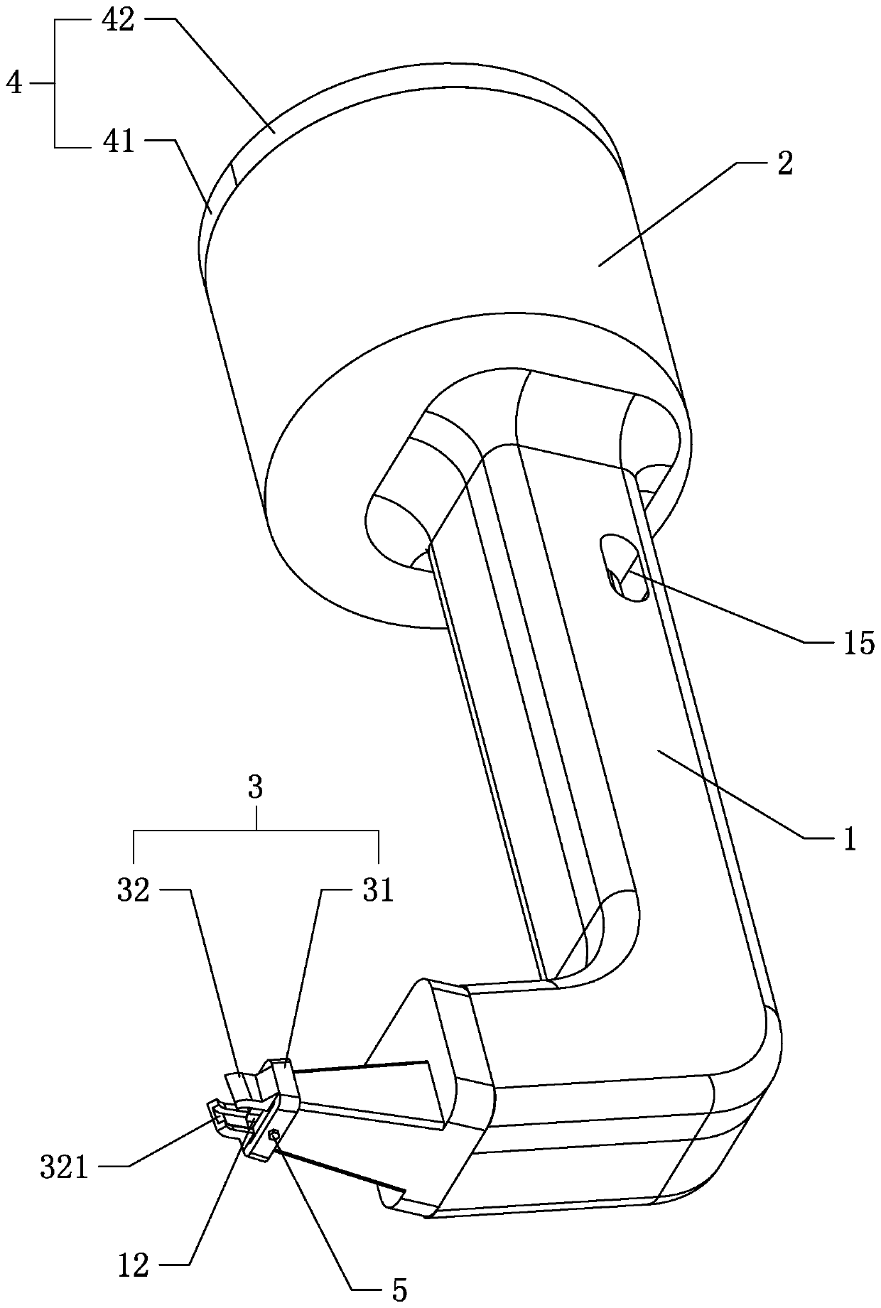
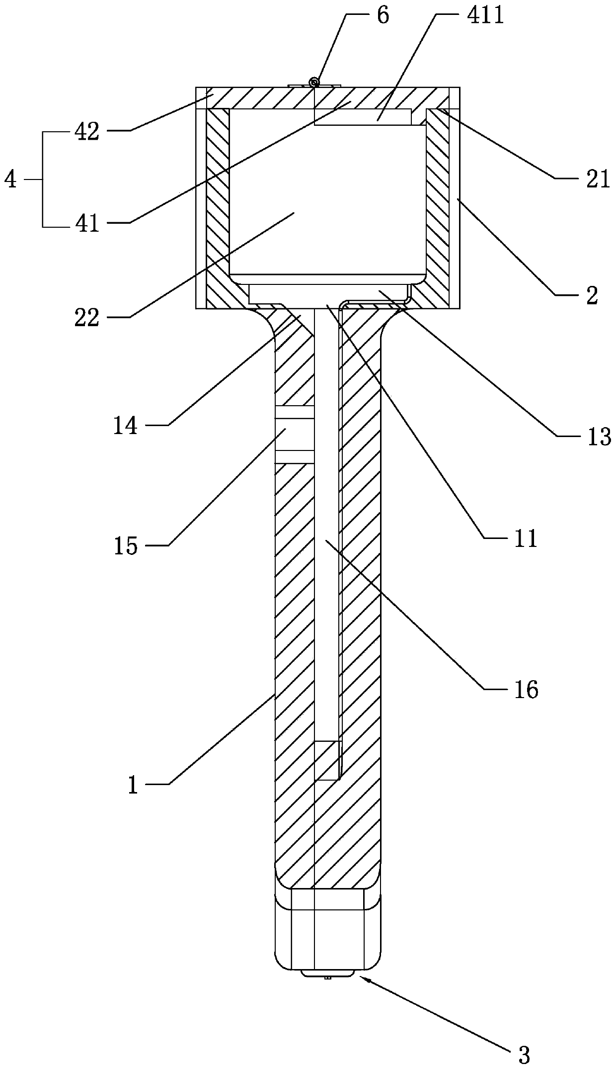
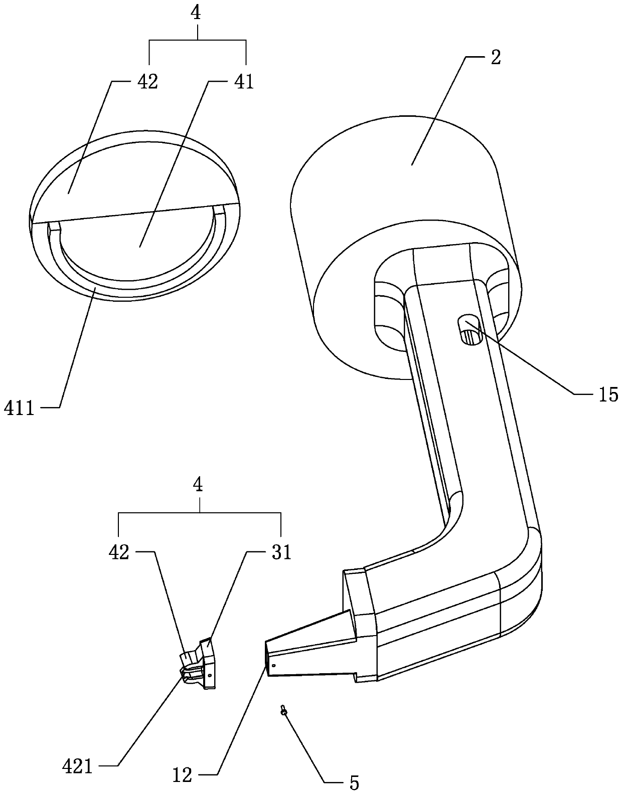
[0041] Example 1: Combining figure 1 and figure 2, is an auxiliary installation tool for shaft sleeve rings disclosed in the present invention, which includes an L-shaped tube body 1, and a track 16 for accommodating the ring body is arranged inside the tube body 1, and the two ends of the tube body 1 are respectively The track 16 is connected to the feed port 11 and the discharge port 12. The length of the long side on the cross section of the track 16 is slightly greater than the outer diameter of the ring body, and the length of the short side is less than the outer diameter of the ring body but slightly greater than the thickness of the ring body. It is convenient for the ring body to slide smoothly from the feed port 11 to the discharge port 12. Preferably, the included angle of the pipeline is 100° to 120°, so that the ring body can be subjected to the gravity of the ring body from the feed port 11 , slide out from the discharge port 12 along the track 16, and enter th...

Embodiment 2

[0051] Embodiment 2: a method for installing a shaft collar disclosed by the present invention, comprising the following steps:

[0052] Step 1, put the ring body in the container 2: turn the second cover plate 42, open the opening 21 of the container 2, put the ring body into the container 2, turn the second cover plate 42, close the opening 21 of the container 2.

[0053] Step 2: The track 16 is full of rings: Press and hold the cover 4, shake the container 2, and you can see the rings in the track 16 along the observation port 15. When the track 16 is full of rings, stop shaking the container 2 .

[0054] Step 3: Install the ring body on the shaft body: the ring body on the jaw 32 is sleeved on the shaft body from one end of the shaft body, and the pipe body 1 is pulled along the radial direction of the shaft body, so that the ring body produces a force on the jaw 32 force, the jaws 32 produce elastic deformation, the ring body is separated from the jaws 32 at the port of ...


PUM


Abstract

The invention relates to an auxiliary mounting tool for a shaft sleeve ring. The auxiliary mounting tool comprises an L-shaped pipe body convenient to handhold, a rail for allowing a ring body to passat a time is arranged in the pipe body, and a feeding port and a discharging port communicating with the rail are formed in the two ends of the pipe body correspondingly. A container which communicates with the rail and is used for storing the ring body is arranged on the feeding port, the side, away from the feeding port, of the container is open, and a clamping part which is elastic and is usedfor clamping the single ring body is arranged at one end of the discharging port. The auxiliary mounting tool has the effect that the shaft sleeve ring can be mounted on a shaft fast.

Description

technical field [0001] The invention relates to the technical field of shaft sleeve ring installation, in particular to an auxiliary installation tool for shaft sleeve rings and a construction method thereof. Background technique [0002] At present, most shafts need to be fitted with shaft collars for use. During use, installing the shaft collars is a problem that needs to be solved. [0003] In the existing design, the Chinese patent whose authorized notification number is CN107414447B discloses a kind of installation equipment for the installation of the central shaft collar of the pipeline muffler, including a base; a feeding mechanism is arranged above the base, and the The feeding mechanism is provided with a feeding plate for the movement of a single shaft collar; the positioning mechanism includes a positioning block arranged obliquely on the base, a mounting tube located at the front end of the positioning block and used to fix the sound-absorbing pipe body, The in...

Claims


Application Information

Patent Timeline
Patent Type & Authority Applications(China)
IPC IPC(8): B23P19/00B23P19/02
CPCB23P19/004B23P19/006B23P19/02
Inventor 韩宁宁
Owner 邱建忠
Why Eureka
Try Eureka