Unlock instant, AI-driven research and patent intelligence for your innovation.

Partition wall-wall connection structure

A technology for connecting structures and walls, which is applied in the direction of walls, building components, building structures, etc., can solve the problems of wear and tear of the contact parts between the wall and the partition wall keel, poor stability of the partition wall keel, and affecting the strength of the connection, etc., to achieve Improving the purpose of moisture resistance and reinforcement, ensuring verticality and stability, and improving the effect of stability

Inactive Publication Date: 2020-06-05
张炜
View PDF6 Cites 1 Cited by
  • Summary
  • Abstract
  • Description
  • Claims
  • Application Information

AI Technical Summary

Problems solved by technology

[0003] However, there are the following problems in the existing connection method between the keel of the partition wall and the body of wall: (1) the installation method is relatively simple. Generally, the keel of the partition wall is directly fixed on the wall by bolts. The contact parts of the keel of the partition wall are worn and easily produce gaps, which makes the keel of the partition wall loose and less stable; (2) the wall at the periphery of the building is exposed to the outside world for a long time, and the moisture and rainwater from the outside easily penetrate into the wall and the keel. The connection of the keel of the partition wall causes damage to the wall structure at the connection and affects the strength of the connection

Method used


Image

  • Partition wall-wall connection structure
  • Partition wall-wall connection structure
  • Partition wall-wall connection structure

Examples


Embodiment Construction

[0022] The following will clearly and completely describe the technical solutions in the embodiments of the present invention with reference to the accompanying drawings in the embodiments of the present invention. Obviously, the described embodiments are only some, not all, embodiments of the present invention. Based on the embodiments of the present invention, all other embodiments obtained by persons of ordinary skill in the art without making creative efforts belong to the protection scope of the present invention.

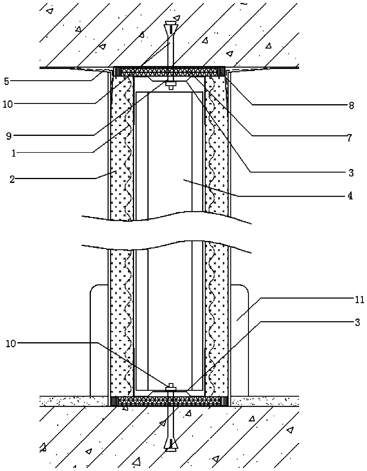
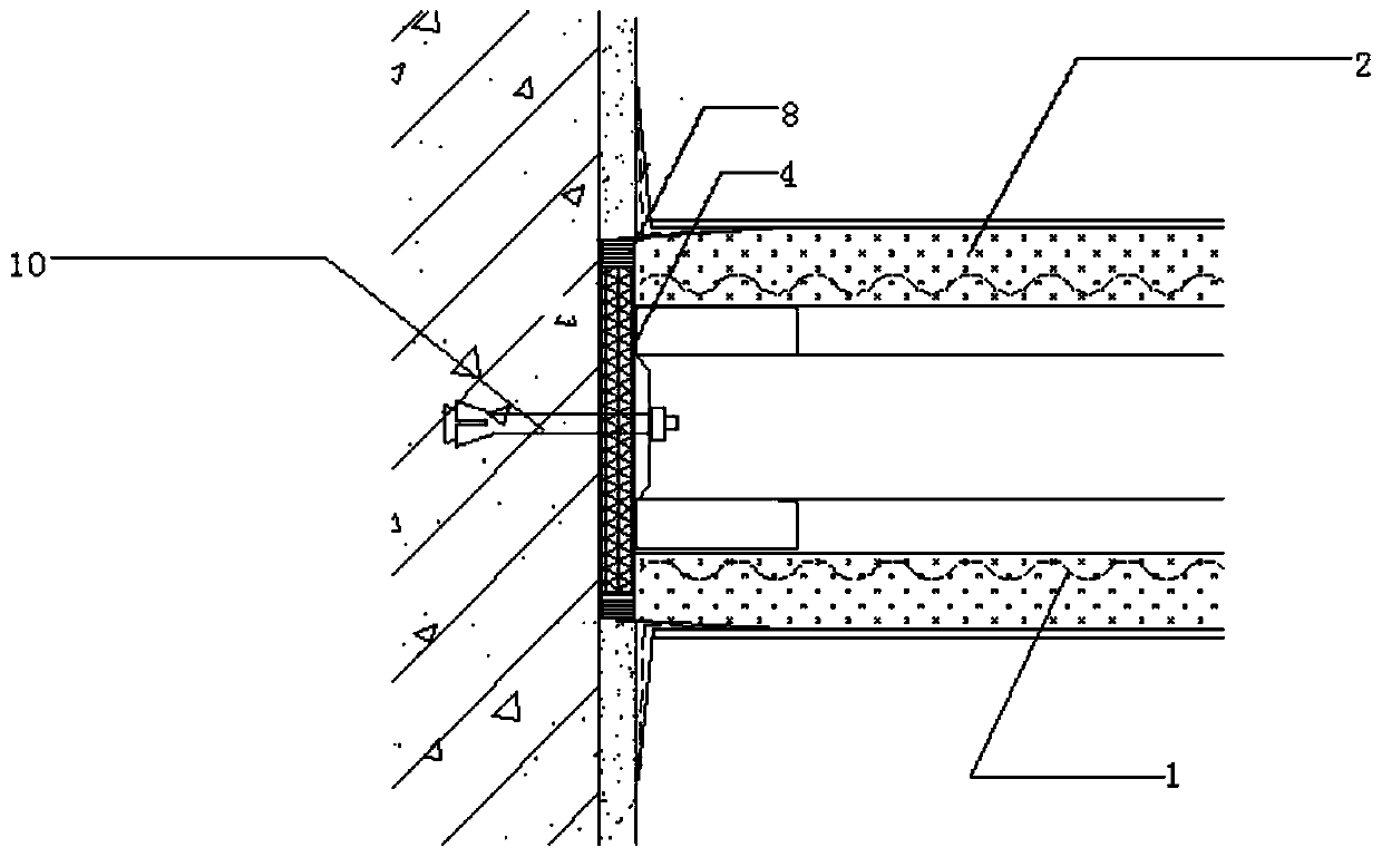
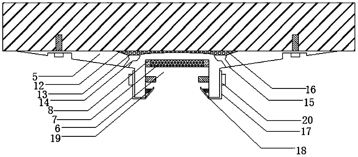
[0023] see Figure 1-4 , the present invention provides a technical solution: a connection structure between a partition wall and a wall body, including a partition wall keel, steel wire mesh 1 is arranged on both sides of the partition wall keel, and a high-performance sprayed wall is sprayed on the outside of the steel wire mesh 1 Body material 2, the keel of the partition wall is composed of two sets of horizontal keels 3 arranged symmetrically up and down ...


PUM


Abstract

The invention discloses a partition wall-wall connection structure comprising a partition wall keel. Steel wire meshes are arranged on the two sides of the partition wall keel correspondingly. High-performance sprayed wall materials are sprayed on the outer sides of the steel wire meshes. The partition wall keel is composed of two transverse keels and multiple vertical keels, wherein the transverse keels are vertically and symmetrically arranged on a wall, and the vertical keels are perpendicularly installed between the two transverse keels. A protection partition plate is installed at the connection position of the transverse keel located on the top and the wall. An installation groove is machined and formed in the middle portion of the protection partition plate. The transverse keel located on the top is horizontally arranged in the installation groove, and a sealing adhesive strip is arranged at the connection position. The two sides of the sealing adhesive strip are filled with a sealant. Punched holes are formed in the connection positions of the transverse keels and the end portions of the vertical keels correspondingly. Expansion bolts are arranged in the punched holes. Theinner ends of the expansion bolts penetrate through the inner portion of the protection partition plate and are fixed in the wall. By means of the partition wall and wall connection structure, the connection structure of the partition wall keel and the wall is improved, the protection partition plate is designed at the connection position of the partition wall keel and the wall, and the installation stability of the partition wall keel can be effectively improved.

Description

technical field [0001] The invention relates to the technical field of building structures, in particular to a connection structure between a partition wall and a wall body. Background technique [0002] The skeleton partition wall is also called the keel partition wall, which mainly uses wood or steel to form the skeleton, and then makes the surface layer on both sides. Simply put, it refers to the installation of panels on both sides of the partition wall keel to form a lightweight partition wall keel, which is composed of upper sills, lower sills, vertical bars, horizontal bars (also known as cross bars), and diagonal braces. The spacing of the vertical ribs depends on the specifications of the materials used, and then use the same cross-section material between the vertical ribs along the height direction, set the horizontal ribs according to the plate specifications, and brace and nail them at both ends to increase stability. The surface materials are usually light thi...

Claims


Application Information

Patent Timeline
IPC IPC(8): E04B2/82E04B1/64E04B1/70E04B1/684
CPCE04B1/644E04B1/68E04B1/6801E04B1/70E04B2/82
Inventor 张炜
Owner 张炜
Features
  • R&D
  • Intellectual Property
  • Life Sciences
  • Materials
  • Tech Scout
  • Unparalleled Data Quality
  • Higher Quality Content
  • 60% Fewer Hallucinations
Learn More