Multi-head branch-control 3D printer

A 3D printer, multi-head technology, used in 3D object support structures, additive manufacturing, coating devices, etc., can solve problems that have not been met, and achieve the effect of improving printing efficiency, strength and stability

Active Publication Date: 2017-09-19
LUOYANG INST OF SCI & TECH
8 Cites 6 Cited by

AI-Extracted Technical Summary

Problems solved by technology

Then, under the background of this excellence, fast-paced and personalized social life, low-cost, hi...

Abstract

The invention discloses a multi-head branch-control 3D printer. Longitudinal guide rails are two guide rails symmetrically distributed along the middle positions of transverse guide rails. Each longitudinal guide rail is symmetrically provided with two printing head mounting sliding blocks, wherein a 3D printing head is mounted on each printing head mounting sliding block. The four 3D printing heads on the two longitudinal guide rails complete printing in four areas of a printing platform. Every time printing of one layer is completed, the printing platform is driven by a power mechanism to rotate by 3.6 degrees, and therefore the printing areas corresponding to the four printing heads are stacked at the joint of the two adjacent printing areas of the lower layer. The four printing heads of the multi-head branch-control 3D printer work at the same time and do not generate interference to one another, and the printing efficiency is greatly improved; and the printing platform is arranged to be rotatable, and therefore after printing work of one layer is completed every time, the printing platform rotates by a certain angle, the printing area of each printing head is changed, staggered stacking between the different printing layers is formed, and the strength and stability of printed products are improved.

Application Domain

Technology Topic

Image

  • Multi-head branch-control 3D printer
  • Multi-head branch-control 3D printer

Examples

  • Experimental program(1)

Example Embodiment

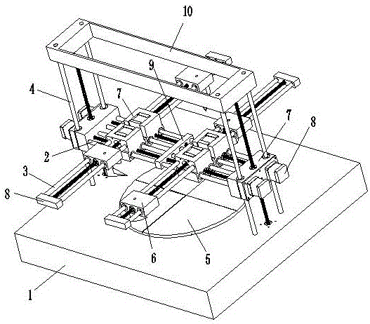
[0018] As shown in the figure, a multi-head sub-control 3D printer includes a printing base 1, a horizontal guide rail 2, a longitudinal guide 3 and a vertical guide 4 arranged on the printing base 1, wherein the two ends of the horizontal guide 2 pass sliding The block screw mechanism slides back and forth on the vertical guide rail 4, and the longitudinal guide 3 slides back and forth on the horizontal guide rail 2 through the slider screw mechanism; the printing base 1 is provided with a printing platform 5 driven by a power mechanism to rotate. The longitudinal guide rails 3 are two guide rails symmetrically distributed along the middle position of the horizontal guide rail 2, and each longitudinal guide rail 3 is symmetrically provided with two print head mounting sliders 6 along its middle position, and each print head mounting slider 6 3D printing heads are mounted on the lower part. The four 3D printing heads on the two longitudinal guides 3 complete the printing in the four areas of the printing platform 5, and each layer of printing is completed, the printing platform 5 is driven by the power mechanism to rotate 3.6 degrees , So that the printing areas of the four print heads are stacked on the junction of two adjacent printing areas on the lower layer.
[0019] The above is the basic implementation of the present invention, and further improvements, optimizations and limitations can be made on the above basis:
[0020] For example, the horizontal guide rails 2 are two guide rails that move synchronously on the vertical guide rails 4, and each longitudinal guide rail 3 is divided into two disconnected parts, and the print head hanger is set by the slider screw mechanism on the two parts. Carrying slider 6; the two parts of each longitudinal guide rail 3 move independently on the transverse guide rail 2 through the slider screw mechanism;
[0021] For another example, the slider screw mechanism includes a slider 7 and a screw 701 threaded with the slider 7. The slider 7 has a cavity for accommodating a motor 704, and the motor 704 drives the screw 701 to rotate, thereby driving the slider 7 moves in the direction of the lead screw 701; on the slider 7 parallel to the lead screw 701 is provided a sliding hole 702 for the guide rail to pass through, so that the slider 7 moves along the lead screw 701 under the guidance of the guide rail; 7 A number of through holes 703 are provided in the direction perpendicular to the lead screw 701 for the guide rail and lead screw in this direction to pass through;
[0022] For another example, the horizontal guide rail 2, the longitudinal guide rail 3 and the vertical guide rail 4 in the present invention can all adopt ball linear guide rails, and the transmission selects the ball screw pair transmission;
[0023] As another example, both ends of the horizontal guide rail 2 and the longitudinal guide rail 3 are provided with a closed guide rail and a head 8 at the end of the screw, and a connecting beam 10 is provided on the top of the vertical guide rail 4.
[0024] Finally, a partition 9 separating the two rails of the longitudinal rail 3 is provided in the middle of the horizontal rail 2.
[0025] In the present invention, a control system needs to be used to uniformly control the working time of the four print heads on each printing layer. The printing speeds of the four print heads can be different, but the working time on each layer must be the same. The minimum time taken by the print head with the largest workload under the premise of ensuring quality is the benchmark, and the print plane of each layer is generated in this mode, so that the separate control of the four print heads is directly coordinated on the instruction. , Next, only need to ensure that each stepper motor can accurately execute the command to realize the multi-head sub-control printing mode;
[0026] But the result just so far is that there will be obvious seams or welds at the junction of the four print heads, which will cause weak links in the printed work. For this reason, after each printing plane is over, the hot bed will go around it. The center is rotated by 3.6 degrees, and the seams are smoothed and welded before the printing of the next layer starts. Each large plane is completed in this way, and the previous vertical seams in the direction of the vertical axis can be perfectly blanked. The subsections are in each layer, and finally form a pressure-seam structure like a bricklaying wall, which reasonably avoids the problem of weak links caused by the partition printing of the four nozzles.
[0027] The print head structure required in the present invention is different from the traditional mechanism. The nozzles of the four print heads need to form a point and line overlap at the normal position of the printing platform, so the four nozzles need to be along the radius of the printing platform toward the printing platform. The center is deflected by an angle of 45°.

PUM

no PUM

Description & Claims & Application Information

We can also present the details of the Description, Claims and Application information to help users get a comprehensive understanding of the technical details of the patent, such as background art, summary of invention, brief description of drawings, description of embodiments, and other original content. On the other hand, users can also determine the specific scope of protection of the technology through the list of claims; as well as understand the changes in the life cycle of the technology with the presentation of the patent timeline. Login to view more.

Similar technology patents

Classification and recommendation of technical efficacy words

  • Improves strength and stability
  • Improve printing efficiency

In-situ heat regeneration remixing and paving technology of asphalt pavement

ActiveCN103590296ASolve the poor connection between layersImproves strength and stabilityIn situ pavingsRoads maintainenceHeat regenerationPitch blende
Owner:CCCC SHEC DONGMENG ENG CO LTD

Auxiliary frame of wheel loader

Owner:SHAANXI SHENGMAI PETROLEUM

3D printing method and 3D printer

InactiveCN103231513AReduce printing timeImprove printing efficiencyThermal printingEngineering
Owner:温州启龙电子科技有限公司
Why Eureka
Try Eureka