3D printing equipment with high-efficiency print head

A 3D printing and printing head technology, applied in the field of powder material forming production devices, can solve the problems of inability to achieve large-scale and industrialized applications, low printing efficiency, and small area.

Active Publication Date: 2014-10-08
NINGXIA KOCEL MOLD
View PDF7 Cites 23 Cited by
  • Summary
  • Abstract
  • Description
  • Claims
  • Application Information

AI Technical Summary

Problems solved by technology

Its disadvantages are: the single printing area of ​​this kind of print head is small, and the printing efficiency is low, about 10L/H. This kind of efficient 3D print

Method used


Image

  • 3D printing equipment with high-efficiency print head
  • 3D printing equipment with high-efficiency print head
  • 3D printing equipment with high-efficiency print head

Examples


Example Embodiment

[0017] Example 1

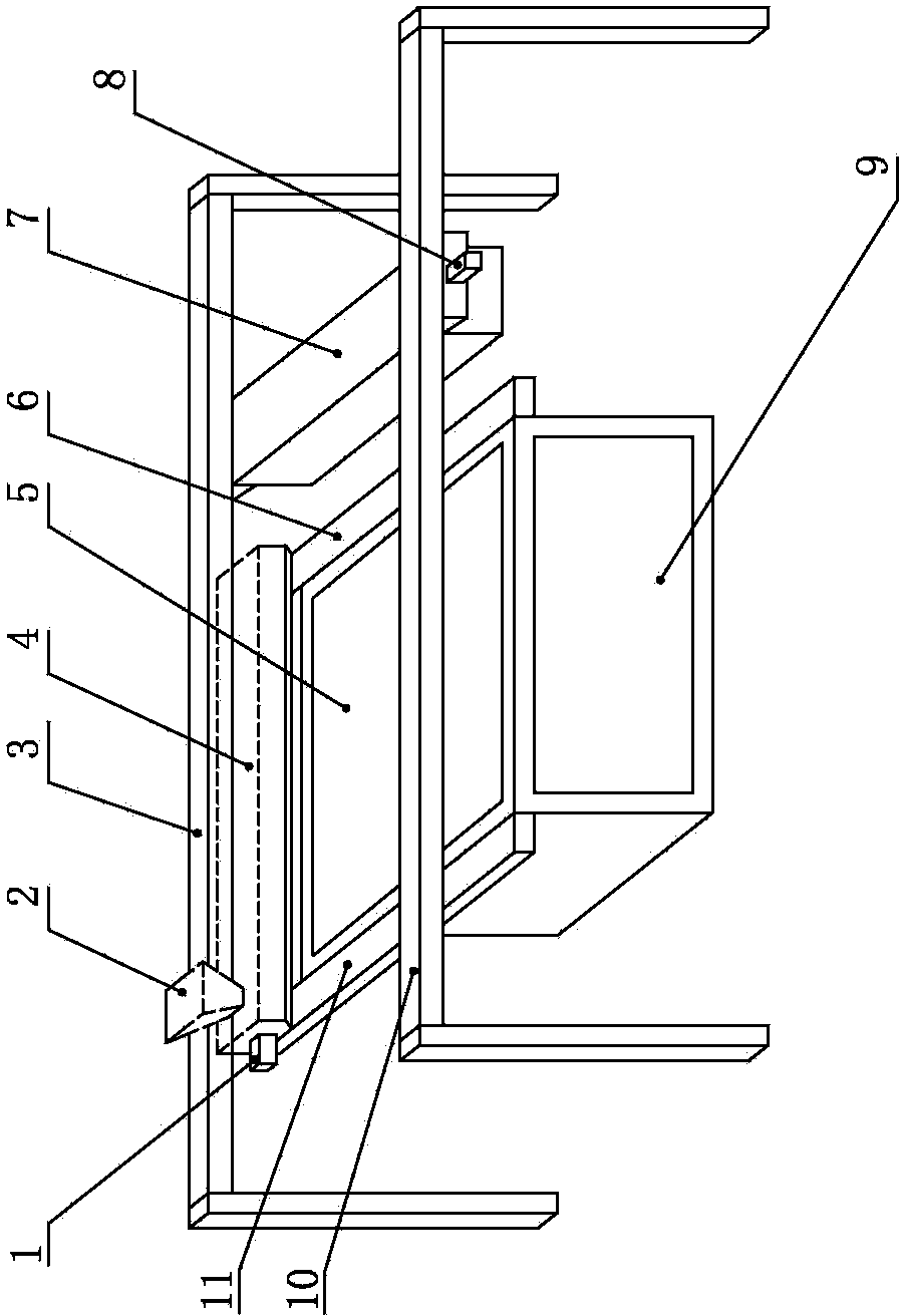
[0018] like figure 1 , 3 As shown in and 4, it is a 3D printing device with a high-efficiency print head, including a powder spreading unit, a printing unit and a work box lifting unit; the powder spreading unit includes a feeding hopper 2, and the feeding hopper 2 is installed above the powder spreading device 4. Both ends of the powder dispenser 4 are installed on the first linear guide rails 6 and 11, and the powder spreader 4 is provided with a first drive mechanism 1 that drives the powder spreader 4 to walk along the first linear guide rails 6 and 11; the printing unit includes a print head 7. The print head 7 is directly installed on the second linear guide rails 3 and 10, and the print head 7 is connected with the second drive mechanism 8 that drives the print head 7 to walk along the second linear guide rails 3 and 10; There are two guide rails 11 and are arranged on both sides of the work box 9 respectively, and there are two second linear guide ...

Example Embodiment

[0022] Example 2

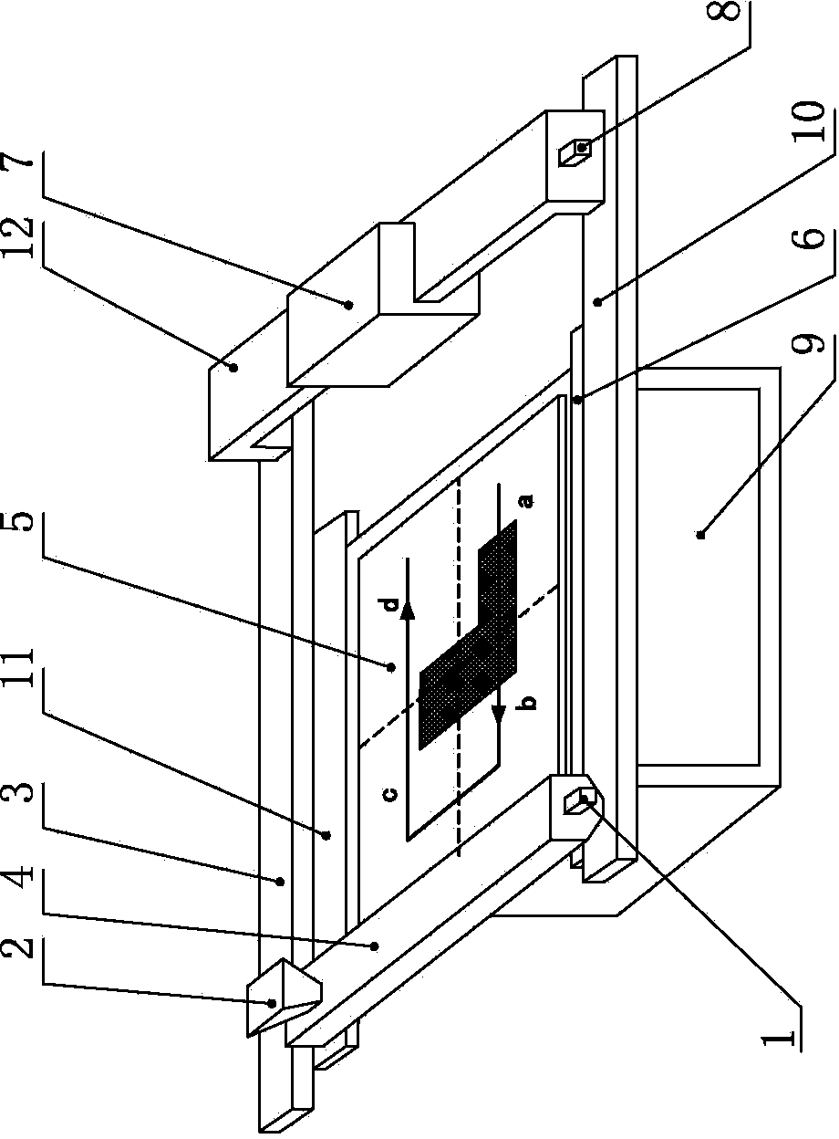
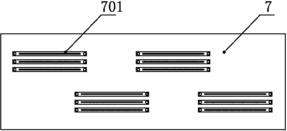
[0023] like figure 2 As shown, it is another 3D printing device with a high-efficiency print head 7, including a powder spreading unit, a printing unit and a work box lifting unit; Both ends of the powder dispenser 4 are installed on the first linear guide rails 6 and 11, and the powder spreader 4 is provided with a first drive mechanism 1 that drives the powder spreader 4 to walk along the first linear guide rails 6 and 11; the printing unit includes The print head 7, the print head 7 is indirectly installed on the second linear guide rails 3 and 10 through the third linear guide rail 12, and the print head 7 is in a transmission connection with the second driving mechanism 8 that drives the print head 7 to walk along the second linear guide rails 3 and 10. The working box lifting unit includes a working box 9, and a lifting platform 5 is arranged in the working box 9; Covering the entire lift platform 5 , a number of independently controllable nozzles 7...


PUM


Abstract

The invention discloses 3D printing equipment with a high-efficiency print head in the field of powder material forming production device. The 3D printing equipment comprises a powder spreading unit, a printing unit and a working box lifting unit, wherein the powder spreading unit comprises a feeding hopper; the feeding hopper is mounted above a powder spreader; the two ends of the powder spreader are mounted on first linear guide rails; a first driving mechanism for driving the powder spreader to move along the first linear guide rails is installed on the powder spreader; the printing unit comprises a print head; the print head is installed on second linear guide rails; the print head is in transmission connection with a second driving mechanism for driving the print head to move along the second linear guide rails; the working box lifting unit comprises a working box; a lifting platform is arranged inside the working box; the powder spreader and the print head are arranged above the lifting platform; the moving areas of the powder spreader and the print head cover the whole lifting platform; a plurality of spray nozzles capable of being independently controlled are formed in the print head. The 3D printing equipment is high in printing efficiency and is applicable to production of a metal casting sand mould.

Description

technical field [0001] The invention relates to a powder material forming production device, in particular to a 3D printing device for casting sand molds. Background technique [0002] In the current sand-type 3D printing equipment, the print head generally adopts the form of single nozzle or double nozzle. The nozzle sprays the binder according to the computer control instructions, and the binder is sprayed on the powder layer mixed with the catalyst and then hardened. The disadvantage is that the single printing area of ​​this type of printing head is small, and the printing efficiency is low, about 10L / H. This kind of efficient 3D printing equipment can only be used in new product experiments and research and development, and it is far from being able to achieve large-scale production. and the stage of industrial application. SUMMARY OF THE INVENTION [0003] The purpose of the present invention is to provide a 3D printing device with a high-efficiency print head, so t...

Claims


Application Information

Patent Timeline
IPC IPC(8): B28B1/00B28B1/24B22C9/02
CPCB22C9/02B28B1/001
Inventor 刘轶
Owner NINGXIA KOCEL MOLD
Why Eureka
Try Eureka