Check patentability & draft patents in minutes with Patsnap Eureka AI!

Spliced display screen

A display screen and rectangular frame technology, applied in the direction of instruments, identification devices, etc., can solve the problems that the display screen cannot achieve the ideal zero gap, the seam design value is reduced, and the edge of the display screen collides, etc., to achieve accurate assembly, save physical strength, The effect of collision avoidance

Active Publication Date: 2020-06-05
BOE TECH GRP CO LTD +1
View PDF9 Cites 0 Cited by
  • Summary
  • Abstract
  • Description
  • Claims
  • Application Information

AI Technical Summary

Problems solved by technology

[0003] However, the stitching of the splicing display screen is the main factor that directly affects the viewing effect of the splicing screen. Now the design splicing value of the splicing screen (that is, the width of the black non-display area between the display areas A-A) has reached 3.5mm, or even 1mm. And developers are constantly challenging the limit to reduce the seam design value
However, in the actual assembly, due to dimensional tolerances and personnel operation problems, the ideal 0 gap between the display screens cannot be achieved, that is, the actual seam will be different from the theoretical gap, which will affect the viewing effect, and even the edge of the display screen will collide during assembly. Display broken corners problem

Method used


Image

  • Spliced display screen
  • Spliced display screen
  • Spliced display screen

Examples


Embodiment Construction

[0047]In order to further explain the technical means and effects of the present invention to achieve the intended purpose of the invention, the specific implementation, structure, features and effects of the spliced ​​display screen proposed according to the present invention will be described below in conjunction with the accompanying drawings and preferred embodiments. , as detailed below. In the following description, different "one embodiment" or "embodiment" do not necessarily refer to the same embodiment. Furthermore, the particular features, structures, or characteristics of one or more embodiments may be combined in any suitable manner.

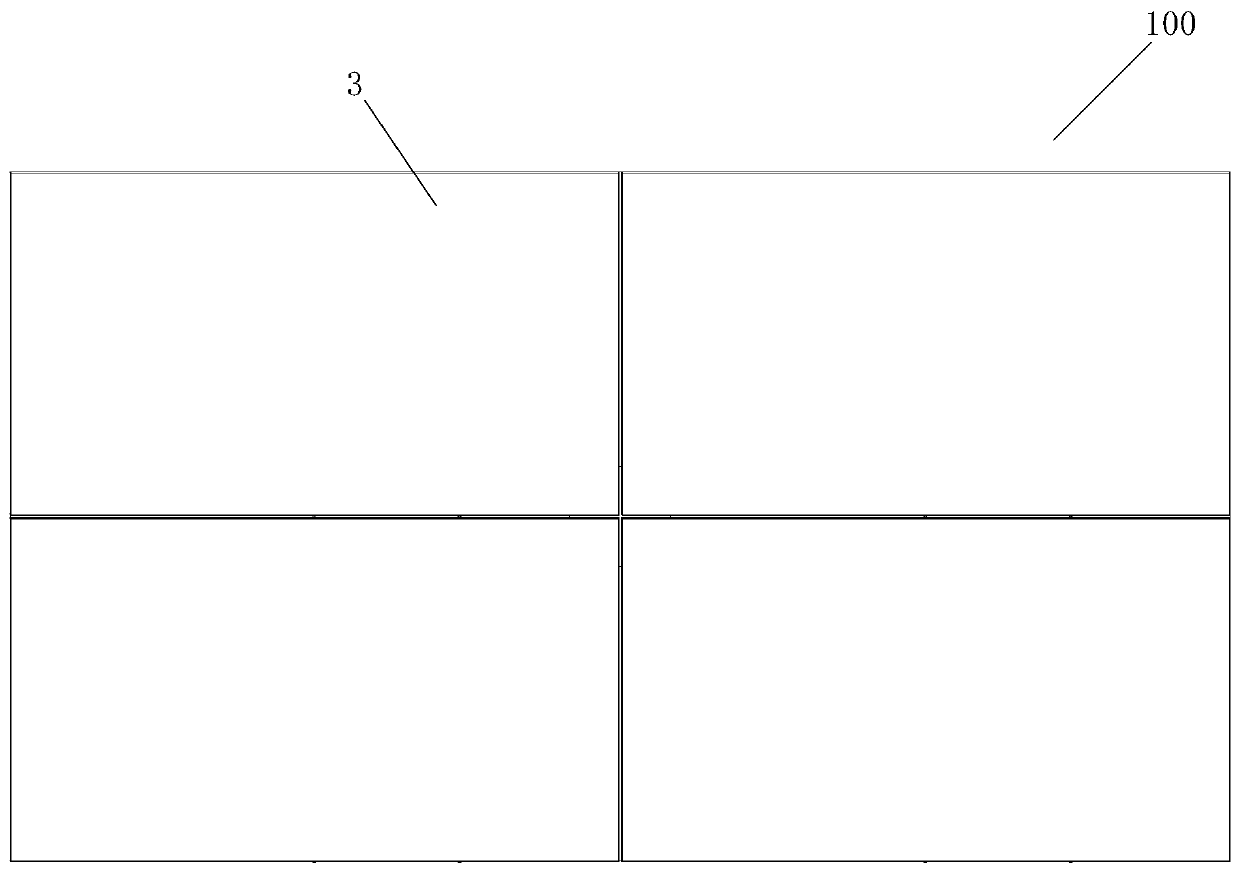
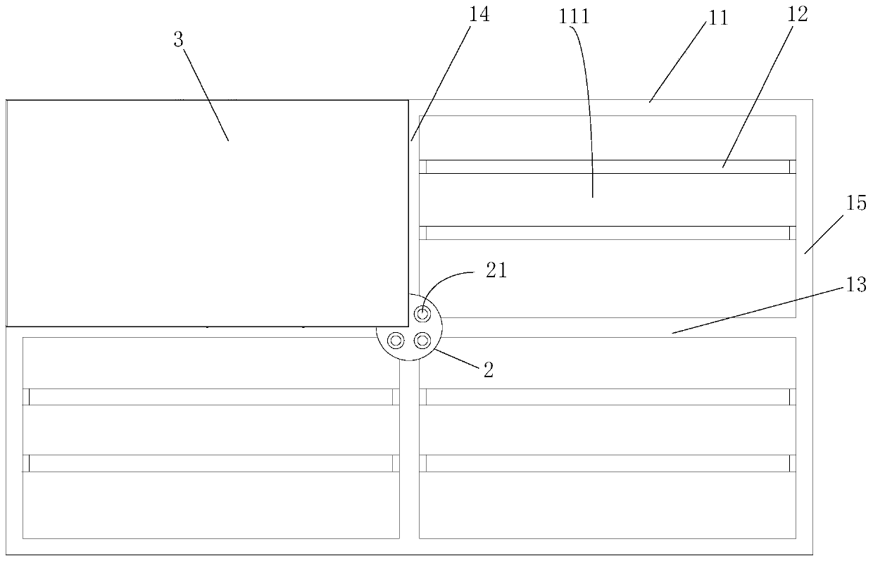
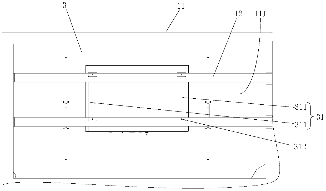
[0048] Such as Figure 1-Figure 5 As shown, the embodiment of the present invention proposes a splicing display screen 100, which includes: a bracket 1, the bracket 1 includes a rectangular frame 11 and a movable beam 12, and the rectangular frame 11 is provided with a beam 13 and / or a longitudinal Beam 14, which separates the rect...


PUM


Abstract

The invention relates to a spliced display screen, and relates to the technical field of display. According to the main technical scheme, the spliced display screen comprises a support, the support comprises a rectangular frame and a movable cross beam, the rectangular frame is internally provided with a cross beam and / or a longitudinal beam to divide the rectangular frame into at least two rectangular frame units, the movable cross beam is arranged in the rectangular frame units, and the two ends of the movable cross beam are movably connected with the rectangular frame units respectively; the limiting part is arranged on the cross beam or the longitudinal beam, and at least two limiting holes are formed in the limiting part; hanging parts and limiting columns are arranged on the backs ofthe display screen single bodies, and the limiting columns are located on the edges of the display screen single bodies; each display screen single body corresponds to each rectangular frame unit, the hanging portions of the display screen single bodies are connected with the movable cross beams in the corresponding rectangular frame units in a hanging mode, and the limiting columns of every twoadjacent display screen single bodies are inserted into the limiting holes of the same limiting portion. The technical problem that in the prior art, the dimensional tolerance of abutted seams is large is solved.

Description

technical field [0001] The invention relates to the field of display technology, in particular to a spliced ​​display screen. Background technique [0002] In the prior art, at least two display screens are placed on the bracket through the back hanger and spliced ​​to form a spliced ​​display screen with a larger display area. [0003] However, the stitching of the splicing display screen is the main factor that directly affects the viewing effect of the splicing screen. Now the design splicing value of the splicing screen (that is, the width of the black non-display area between the display areas A-A) has reached 3.5mm, or even 1mm. And developers are constantly challenging the limit to reduce the seam design value. However, in the actual assembly, due to dimensional tolerances and personnel operation problems, the ideal 0 gap between the display screens cannot be achieved, that is, the actual seam will be different from the theoretical gap, which will affect the viewing ...

Claims


Application Information

Patent Timeline
IPC IPC(8): G09F9/302
CPCG09F9/302
Inventor 王馨蕊石海军
Owner BOE TECH GRP CO LTD
Features
  • R&D
  • Intellectual Property
  • Life Sciences
  • Materials
  • Tech Scout
  • Unparalleled Data Quality
  • Higher Quality Content
  • 60% Fewer Hallucinations
Learn More