
Wireless charging circuit and parameter selection method thereof for realizing constant-power wireless charging

A technology of wireless charging and parameter selection, applied in the direction of battery circuit devices, circuit devices, collectors, etc., to achieve the effect of constant power charging

Active Publication Date: 2020-06-05
SICHUAN AEROSPACE SYST ENG INST
View PDF6 Cites 2 Cited by
  • Summary
  • Abstract
  • Description
  • Claims
  • Application Information

AI Technical Summary

Problems solved by technology

At present, there is no suitable wireless charging structure to directly supply power to electric devices operating at constant power

Method used


Image

  • Wireless charging circuit and parameter selection method thereof for realizing constant-power wireless charging
  • Wireless charging circuit and parameter selection method thereof for realizing constant-power wireless charging
  • Wireless charging circuit and parameter selection method thereof for realizing constant-power wireless charging

Examples


Embodiment

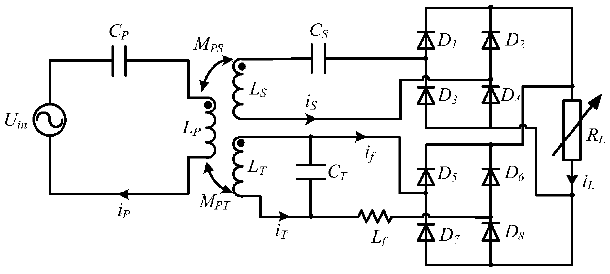
[0034] like figure 1 As shown, a wireless charging circuit includes a first S-resonance compensation circuit provided on the primary side, a second S-resonance compensation circuit and an LCL resonant compensation circuit provided on the secondary side, the first S-resonance compensation circuit includes a series Set the first resonance compensation capacitor C P and the first energy transfer coil L P , the input end of the first S resonant compensation circuit is connected to an AC high-frequency power supply U in ; The second S resonance compensation circuit includes a second resonance compensation capacitor C arranged in series S and the second energy transfer coil L S , the LCL resonance compensation circuit includes a third energy transmission coil L arranged in series T and inductance L f , the third energy transfer coil L T There is a third resonant compensation capacitor C connected in parallel at both ends of T , the output ends of the second S resonant compens...


PUM


Abstract

The invention discloses a wireless charging circuit. The wireless charging circuit comprises a first S resonance compensation circuit arranged on a primary side, a second S resonance compensation circuit arranged on a secondary side and an LCL resonance compensation circuit. The first S resonance compensation circuit comprises a first resonance compensation capacitor and a first energy transmission line which are arranged in series; the second S resonance compensation circuit comprises a second resonance compensation capacitor and a second energy transmission coil which are connected in series; the LCL resonance compensation circuit comprises a third energy transmission coil and an inductor which are arranged in series; the two ends of the third energy transmission coil are connected witha third resonance compensation capacitor in parallel; and the output end of the second S resonance compensation circuit and the output end of the LCL resonance compensation circuit are connected withrectifying circuits respectively. The invention further provides a parameter selection method for realizing constant-power wireless charging of the wireless charging circuit. According to the invention, power is directly supplied to electric equipment operating at constant power; a battery is not used any more; and the cost is saved.

Description

technical field [0001] The invention relates to the technical field of wireless charging, in particular to a wireless charging circuit and a parameter selection method for realizing constant power wireless charging. Background technique [0002] In recent years, wireless charging technology has attracted widespread attention from all walks of life and has developed rapidly due to its safety, reliability, convenience, and no plugging and mechanical wear during use, which can effectively improve the service life of equipment. [0003] At present, the output of most wireless charging systems is constant current or constant voltage, which is only suitable for charging the battery first, and then the battery supplies power to the electrical equipment. When the power of electrical equipment is large, more batteries are needed, which will greatly increase the cost; at the same time, the use of battery-powered indirect power supply is not suitable for some equipment with constant po...

Claims


Application Information

Patent Timeline
IPC IPC(8): H02J7/02H02J7/04H02J7/00H02J50/12
CPCH02J7/04H02J50/12
Inventor 石瑞赵玉强普承恩付颖峰崔允红王丰秋赖玉敏
Owner SICHUAN AEROSPACE SYST ENG INST
Learn More