Frame with foldable spare wheel carrier crank support

A technology of spare tire rack and frame, which is applied in the field of frame with foldable spare tire rack crank bracket, and can solve the problems of small crank bracket with no practical effect, waste of materials, and too long distance

Active Publication Date: 2020-06-09
SNTO TECH GRP
View PDF5 Cites 0 Cited by
  • Summary
  • Abstract
  • Description
  • Claims
  • Application Information

AI Technical Summary

Problems solved by technology

The deficiency of the related technology is that, since the operator needs to operate the crank handle at the side of the van, the distance between the force point

Method used


Image

  • Frame with foldable spare wheel carrier crank support
  • Frame with foldable spare wheel carrier crank support
  • Frame with foldable spare wheel carrier crank support

Examples


Embodiment 1

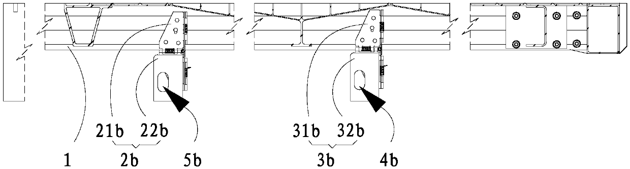
[0022] Please refer to figure 1 , a vehicle frame with a foldable spare tire rack handle bracket, comprising a frame girder 1 and a foldable spare tire rack crank handle bracket located on the vehicle frame girder 1; the vehicle frame girder 1 is two oppositely arranged, the present The application for a vehicle frame with a foldable spare tire rack crank bracket also includes a frame connecting plate arranged between two frame beams 1, and the lower end of the frame connecting plate is provided with a double tire spare tire rack crank Double spare tire carrier with holes, the other end of the bottom of the frame connecting plate is provided with a single tire spare wheel carrier with a hole for the handle of the single tire spare wheel carrier; the foldable spare wheel handle bracket includes a double tire foldable spare wheel carrier Crank bracket 2b, double-tire foldable spare tire rack The crank bracket 2b includes a second mounting plate 21b fixed on the frame frame 1 and...

Embodiment 2

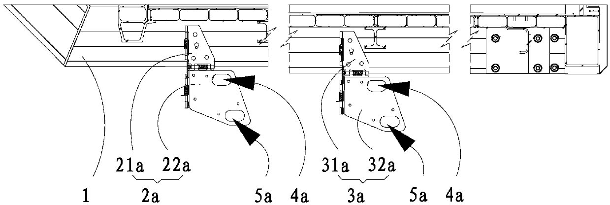
[0025] Please refer to figure 2 , a vehicle frame with a foldable spare tire rack crank bracket, a vehicle frame with a foldable spare tire rack crank bracket, including a frame frame 1 and a foldable spare tire frame crank set on the frame frame 1 Handle brackets; the two frame girders 1 are oppositely arranged, and a vehicle frame with a foldable spare tire rack handle bracket in the present application also includes a frame connecting plate arranged between the two frame girders 1, and the vehicle frame The lower end of the connecting plate is provided with a twin-tire spare tire rack with a handle hole for a twin-tire spare tire rack, and the other end below the frame connecting plate is provided with a single-tire spare tire rack with a handle hole for a single-tire spare tire rack; The foldable spare tire rack crank bracket includes a twin tire foldable spare tire rack crank bracket 2a, and the twin tire foldable spare tire rack crank bracket 2a includes a second mounti...


PUM


Abstract

The invention discloses a frame with a foldable spare wheel carrier crank support. The frame comprises a frame girder and the foldable spare wheel carrier crank support arranged on the frame girder; the foldable spare wheel carrier crank support comprises an installation plate fixed to the frame girder and a crank frame plate hinged to the lower portion of the installation plate; and a crank holepenetrating through the crank frame plate is formed in the crank frame plate. The foldable spare wheel carrier crank support is arranged at the position, close to the side edge of a compartment body,of the girder, so operation of an operator is facilitated. The position of the crank hole, namely the stress point, is close to the position of the force application point of the hand of the operator,and the supporting effect of the spare tire support can be improved. In addition, the crank frame plate is unfolded when needed and can be folded when not used, so the overall compactness of a wholevehicle is not affected. A hinge between the mounting plate and the crank frame plate is made of existing hardware product, so manufacturing is simple. A hole site of the hole for the crank to penetrate through in the crank frame plate can be customized freely, so universality is high.

Description

technical field [0001] The invention belongs to the technical field of vehicle manufacturing, and in particular relates to a vehicle frame with a foldable crank handle bracket for a spare tire frame Background technique [0002] In the design and production of vans, a spare tire needs to be installed under the car body, and a spare tire lifter needs to be installed at the same time to realize the lifting of the spare tire, and the control of the spare tire lifter is realized through the crank handle. Since the spare tire is arranged at the lower part of the box body and is far away from the edge of the car body, it is necessary to provide force support through the crank bracket. In the related art, the crank bracket is installed on the web of the frame. The disadvantage of the related technology is that since the operator needs to operate the crank handle at the side of the van, the distance between the force point of the crank handle and the fulcrum provided by the handle ...

Claims


Application Information

Patent Timeline
IPC IPC(8): B62D43/00B62D43/04
CPCB62D43/002B62D43/04
Inventor 刘延韬刘威
Owner SNTO TECH GRP
Why Eureka
Try Eureka