Gas explosion simulation test device and system in the space of underground utility tunnel

An explosion simulation and integrated pipe gallery technology, which is applied in the direction of measuring devices, fuel oil testing, and blasting force measurement, can solve problems such as the inability to ensure the smoothness of the pipeline, the inability to study the dynamic response of the pipe gallery structure, and the inability to splice the pipe gallery model, etc.

Active Publication Date: 2022-05-10
ARMY ENG UNIV OF PLA
View PDF16 Cites 0 Cited by
  • Summary
  • Abstract
  • Description
  • Claims
  • Application Information

AI Technical Summary

Problems solved by technology

[0004] At present, many scholars have conducted extensive and in-depth research on the gas explosion process and its destructive effects on engineering structures, and have also developed corresponding test devices for combustion and explosion of premixed gas in pipelines, but such test devices also have certain limitations. :
[0005] 1. This type of test device cannot freely select and assemble the required pipeline segments, so as to realize the transformation of pipeline length, observation window position and explosion vent hole position;
[0006] 2. It is difficult for this type of test device to change the size of the explosion venting area, the location of the explosion venting, and the direction of the explosion venting;
[0007] 3. This type of test device cannot ensure that the inside of the pipeline is completely flat and smooth, and it is also difficult to change the form, position and number of obstacles in the pipeline;
[0008] 4. It is difficult for this type of test device to realize the free change of the volume of combustible gas in the pipeline;
[0009] 5. This type of test device can only obtain the load of the gas explosion in the test pipeline, but cannot splice the pipe gallery model, and cannot study the structural dynamic response of the pipe gallery when the gas explosion in the pipeline

Method used


Image

  • Gas explosion simulation test device and system in the space of underground utility tunnel
  • Gas explosion simulation test device and system in the space of underground utility tunnel
  • Gas explosion simulation test device and system in the space of underground utility tunnel

Examples


Embodiment 1

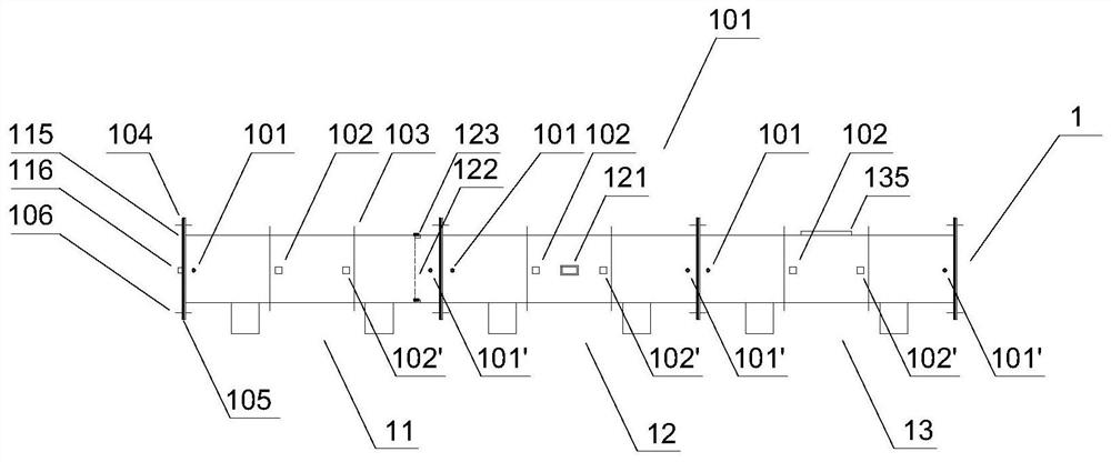
[0062] Embodiment one, as figure 1 As shown, this embodiment provides a gas explosion simulation test device in the space of an underground comprehensive pipe gallery, including a test pipe (1), the test pipe (1) is connected at both ends and includes a basic pipe (11); the basic pipe (11) Both ends are connected and flanges (104) are provided;

[0063] The basic pipeline (11) reserves at least two through holes, such as figure 1 As shown, in this embodiment, the basic pipeline (11) reserves an air inlet (101) and an air outlet (101 , ), the air inlet (101) and air outlet (101 , ) is used to install the embedded module, the embedded module includes obstacles, gas supply mixing system or ignition head; as a preference, in this embodiment, the third through hole and the fourth through hole are set on the basic pipeline (11), that is, the gas concentration Monitoring port (102) and sensor installation port (102 , ).

[0064] Such as figure 1 The gas explosion simulation tes...

Embodiment 2

[0070] Embodiment two, on the basis of above embodiment, as figure 2 As shown, this embodiment provides a gas explosion simulation test device in the space of an underground comprehensive pipe gallery, including: a test pipe (1), the test pipe (1) is connected at both ends and includes an explosion venting pipe (13); the explosion venting pipe Both ends of (13) are connected and flanges (104) are provided at both ends, and the explosion venting pipe and other adjacent components are sealed and connected through sealing flanges; the explosion venting pipe (13) reserves an air inlet (101) and air outlet (101 , ), air inlet (101) and air outlet (101 , ) is used to install the embedded module, the embedded module includes obstacles, gas supply mixing system or ignition head; the gas concentration monitoring port (102) and the sensor installation port (102) are set on the explosion vent pipe , ). figure 2 It shows that the test pipeline (1) also includes a basic pipeline (11) ...

Embodiment 3

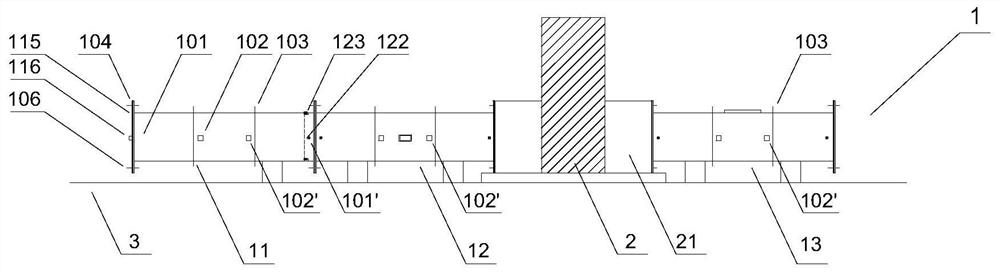
[0075] Embodiment three, on the basis of above embodiment, as image 3 As shown, this embodiment provides a gas explosion simulation test device in the space of an underground comprehensive pipe gallery, including: a test pipe (1) and a transition member (2); the test pipe (1) is connected at both ends, and includes a basic pipe (11), an observation duct (12) and an explosion venting duct (13);

[0076] Both ends of the basic pipeline (11), the observation pipeline (12) and the explosion-venting pipeline (13) are connected and flanges (104) are arranged at both ends, and the foundation pipeline (11), the observation pipeline (12) or the explosion-venting pipeline (13) are sealed and connected with other adjacent components through sealing flanges; the observation pipe (12) is provided with an observation window (121);

[0077] The basic pipeline (11), observation pipeline (12) and explosion venting pipeline (13) are all reserved for installing obstacles or for air inlet (101)...


PUM


Abstract

The invention provides a gas explosion simulation test device and system in the space of an underground comprehensive pipe gallery. The device includes: a test pipeline, the two ends of the test pipeline are connected, and at least one of a basic pipeline, an observation pipeline and an explosion relief pipeline is included. The basic pipeline, the observation pipeline or the explosion-venting pipeline are connected in any combination and order; the test pipeline of the present invention is connected by a flange, the length of the test device can be changed according to the test needs, the number and position of the explosion-venting pipeline can be selected, and through the reserved through hole, It realizes the flexible selection of inflatable position, realizes the test simulation under various working conditions, obtains the load of the gas explosion in the test pipeline, or connects the test pipe gallery to measure the structural response of the pipe gallery.

Description

technical field [0001] The invention belongs to the technical field of combustible gas explosion tests, in particular to a test device capable of simulating gas explosions inside urban underground comprehensive pipe galleries. Background technique [0002] As a shared tunnel for municipal pipelines, the underground comprehensive utility gallery realizes the comprehensive utilization and resource sharing of urban underground space, well solves the phenomenon of "pull link" in municipal construction, and improves the safety of municipal pipeline operation and the convenience of maintenance . At present, the underground comprehensive utility corridor has become an important infrastructure for building a new type of sustainable development city. In the context of my country's rapid urbanization, pilot projects for the construction of underground comprehensive pipe corridors have been launched one after another, and the development of the industry has entered the take-off stage....

Claims


Application Information

Patent Timeline
Patent Type & Authority Patents(China)
IPC IPC(8): G01M99/00G01M13/00G01N3/313G01N21/3504G01N21/84G01N33/22G01L5/14
CPCG01M99/007G01M13/00G01N3/313G01N21/3504G01L5/14G01N21/84G01N33/225G01N2021/8411G01N2203/001
Inventor 方秦李展陈力刘洋
Owner ARMY ENG UNIV OF PLA
Why Eureka
Try Eureka