Jig turnover device
A technology of jig and turnover cart, applied in the direction of manufacturing tools, transportation and packaging, multi-axis trolley, etc., can solve problems such as affecting normal production, damage to the jig, and reduction of the quality and stability of the jig
- Summary
- Abstract
- Description
- Claims
- Application Information
AI Technical Summary
Problems solved by technology
Method used
Image
Examples
Embodiment 1
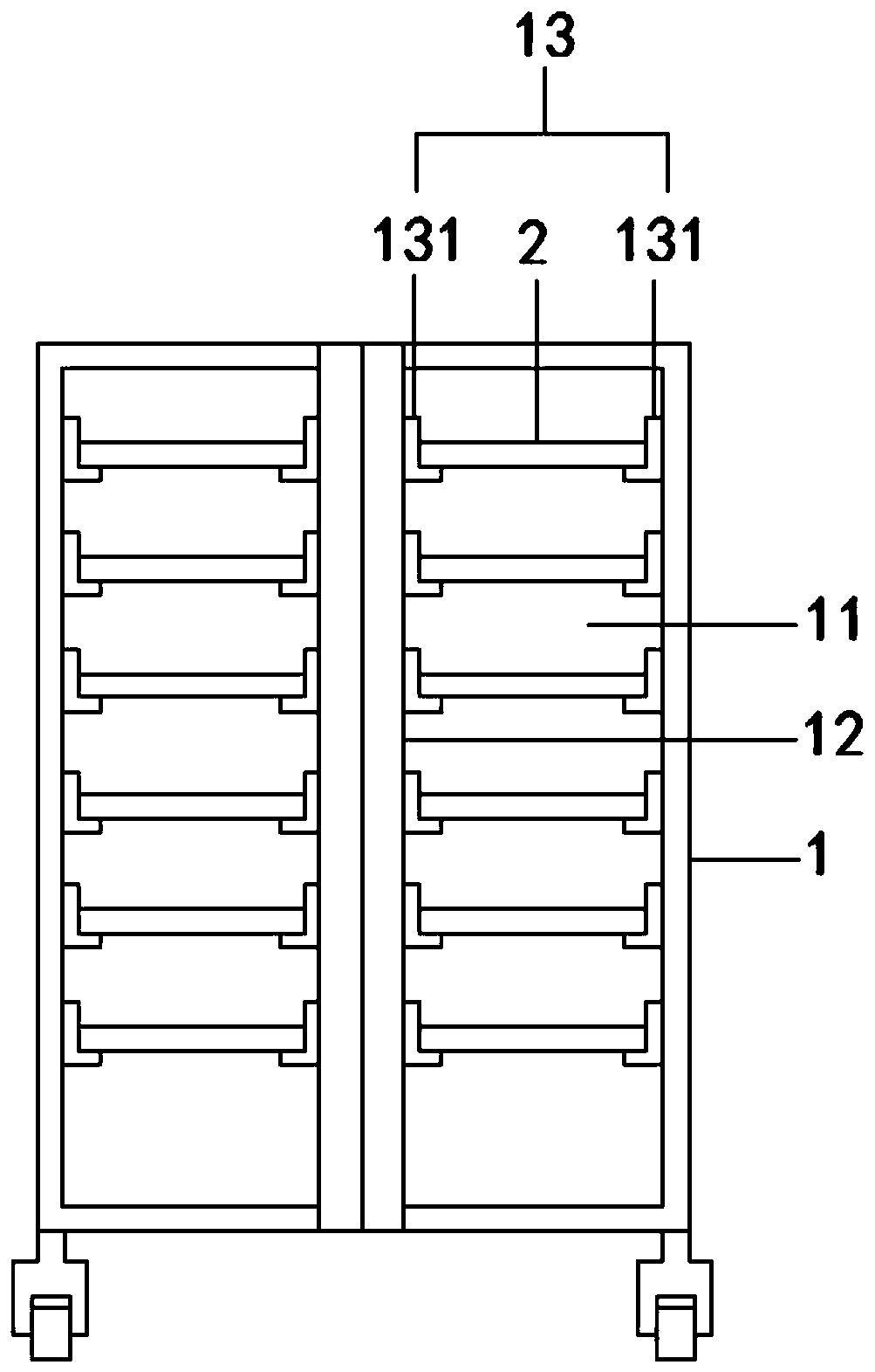
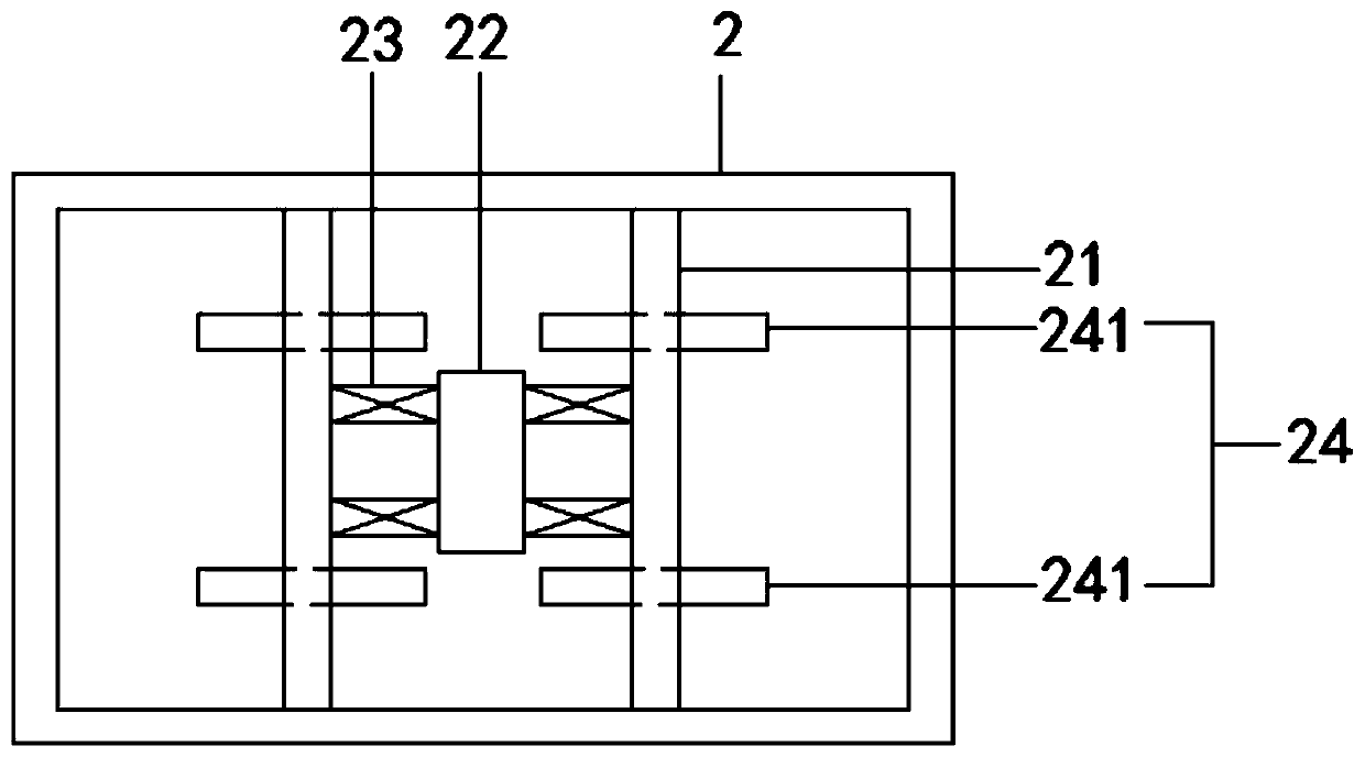
[0023] see Figure 1 to Figure 3 , this embodiment provides a fixture turnover device. First, a turnover car 1 and a plurality of trays 2 are set. At least two tray positioning units 11 are arranged on the turnover car 1, and each tray positioning unit 11 is detachable. A plurality of trays 2 are installed, and at least two partitions 21 are elastically installed in the tray 2. The two partitions 21 divide the tray 2 into at least two positioning cavities, and the volume of the positioning cavity is elastically retracted by the partitions 21. It expands or shrinks under the action, and at least one fixture body is positioned in each positioning cavity.
[0024] continue to see Figure 1 to Figure 3 , a separation bar 12 is detachably installed on the turnover car 1, and the turnover car 1 is divided into two pallet positioning units 11 by the separation rod 12, and the two tray positioning units 11 are located at the left and right ends of the turnover car 1 or at the At the...
Embodiment 2
[0029] see Figure 1 to Figure 3 , the figure shows a fixture turnover device provided by the second embodiment of the present invention. On the basis of the above-mentioned embodiments, this embodiment has further made the following technical solutions as improvements: the tray positioning unit 11 is fixed inside the A plurality of mounting seats 13 are installed, and the tray 2 is snapped into the mounting seats 13. The mounting seat 13 includes two symmetrically arranged concave-shaped plates. Compared with the L-shaped plate in the first embodiment, the concave-shaped plate has better clamping receive effect.
Embodiment 3
[0031] see Figure 1 to Figure 3 , the figure shows a fixture turnover device provided by the third embodiment of the present invention. This embodiment has further made the following technical solutions as improvements on the basis of the above-mentioned embodiments: The turnover car 1 is detachable. A spacer bar 12 is installed on the ground, and the turnover car 1 is divided into two pallet positioning units 11 by the spacer bar 12. Both ends of the spacer bar 12 are fixedly connected with a hoop, and the hoop is tightly wound on the frame of the turnover car 1. The reasons for using the hoop to install the isolation rod 12 on the turnover car 1 are: 1. The hoop is easy to disassemble and assemble; 2. The hoop can be applied to frames of different thicknesses and has strong versatility.
PUM
 Abstract
Description
Claims
Application Information
 - R&D
- Intellectual Property
- Life Sciences
- Materials
- Tech Scout
- Unparalleled Data Quality
- Higher Quality Content
- 60% Fewer Hallucinations
Browse by: Latest US Patents, China's latest patents, Technical Efficacy Thesaurus, Application Domain, Technology Topic, Popular Technical Reports.
© 2025 PatSnap. All rights reserved.Legal|Privacy policy|Modern Slavery Act Transparency Statement|Sitemap|About US| Contact US: help@patsnap.com


