

Telescopic belt conveyor
A telescopic belt conveyor and telescopic mechanism technology, applied in conveyors, transportation and packaging, etc., can solve the problems of wasting human resources, low precision of manual palletizing, and increasing production costs.
- Summary
- Abstract
- Description
- Claims
- Application Information
AI Technical Summary
Problems solved by technology
Method used
Image

Examples
Embodiment Construction
[0019] Referring to the accompanying drawings, through the description of the embodiments, the specific implementation of the present invention, such as the shape, structure, mutual position and connection relationship between the various parts, the function and working principle of each part, and the manufacturing process And the method of operation and use, etc., are described in further detail to help those skilled in the art have a more complete, accurate and in-depth understanding of the inventive concept and technical solution of the present invention.
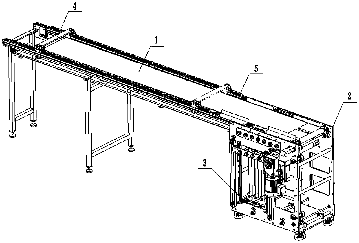
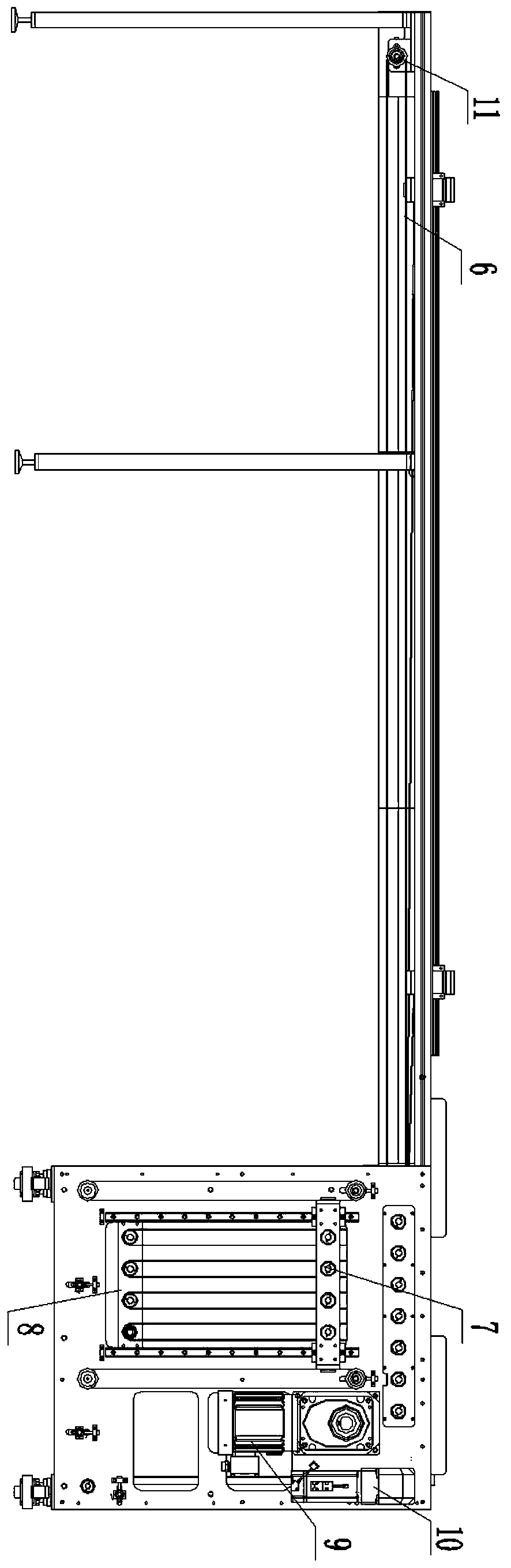
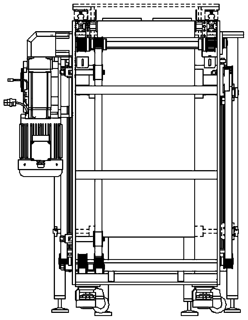
[0020] figure 1 It is a schematic diagram of a retractable belt conveyor in the present invention. A retractable belt conveyor as shown in the figure includes a belt 1 and a frame 2 for supporting the belt conveyor. One end of the frame 2 is provided with a belt for controlling the belt 1 A telescopic telescopic mechanism 3, the end of the belt 1 away from the telescopic mechanism is provided with a sliding connection bl...
PUM
 Abstract
Description
Claims
Application Information