
Refrigeating plant for container

A freezing device and container technology, which is applied in compactness. It can solve the problems of uneven freezing, difficulty in cleaning the container room, and wet goods.

Inactive Publication Date: 2006-12-06
SEIREI IND CO LTD +1
View PDF0 Cites 0 Cited by
  • Summary
  • Abstract
  • Description
  • Claims
  • Application Information

AI Technical Summary

Problems solved by technology

[0015] As the 4th problem of the conventional refrigerator for container, although the wind deflector 123 of the above-mentioned shape distributes the cold air toward the left and right, and the cold air is widely spread toward the left and right through the bottom plate passage 128, but the vertical shape from the left and right is reached. The cold air from the wind control panels 124 in the left and right center and the floor duct 128 in the left and right center where the cold air passage is separated is not enough to reliably refrigerate the left and right central parts of the interior of the container 100, and the entire interior of the container 100 is not uniformly refrigerated.
[0016] In addition, the opening space for opening the door 127a or 127b is narrow, and it is difficult to clean the container room.
In addition, condensed water may accidentally leak into the container interior from the open space formed by opening the door 127a or 127b, and wet the cargo in the container.

Method used


Image

  • Refrigeating plant for container
  • Refrigeating plant for container
  • Refrigeating plant for container

Examples


Embodiment Construction

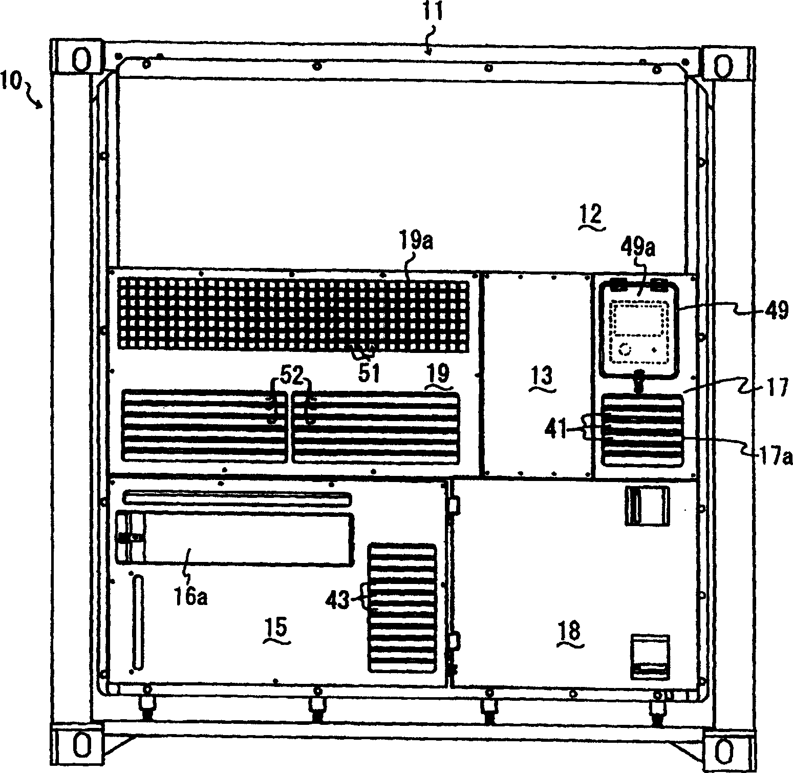
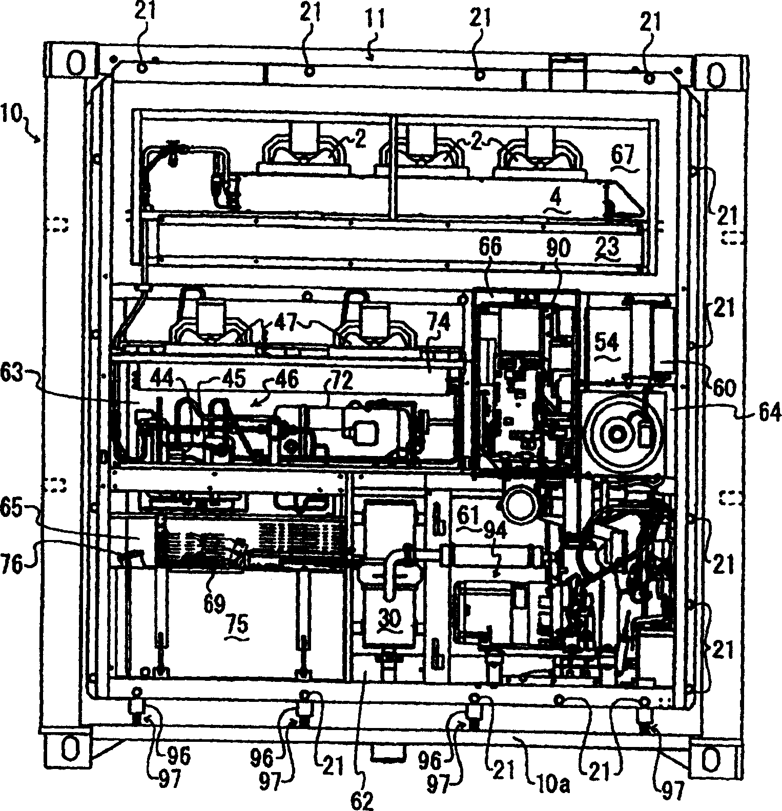
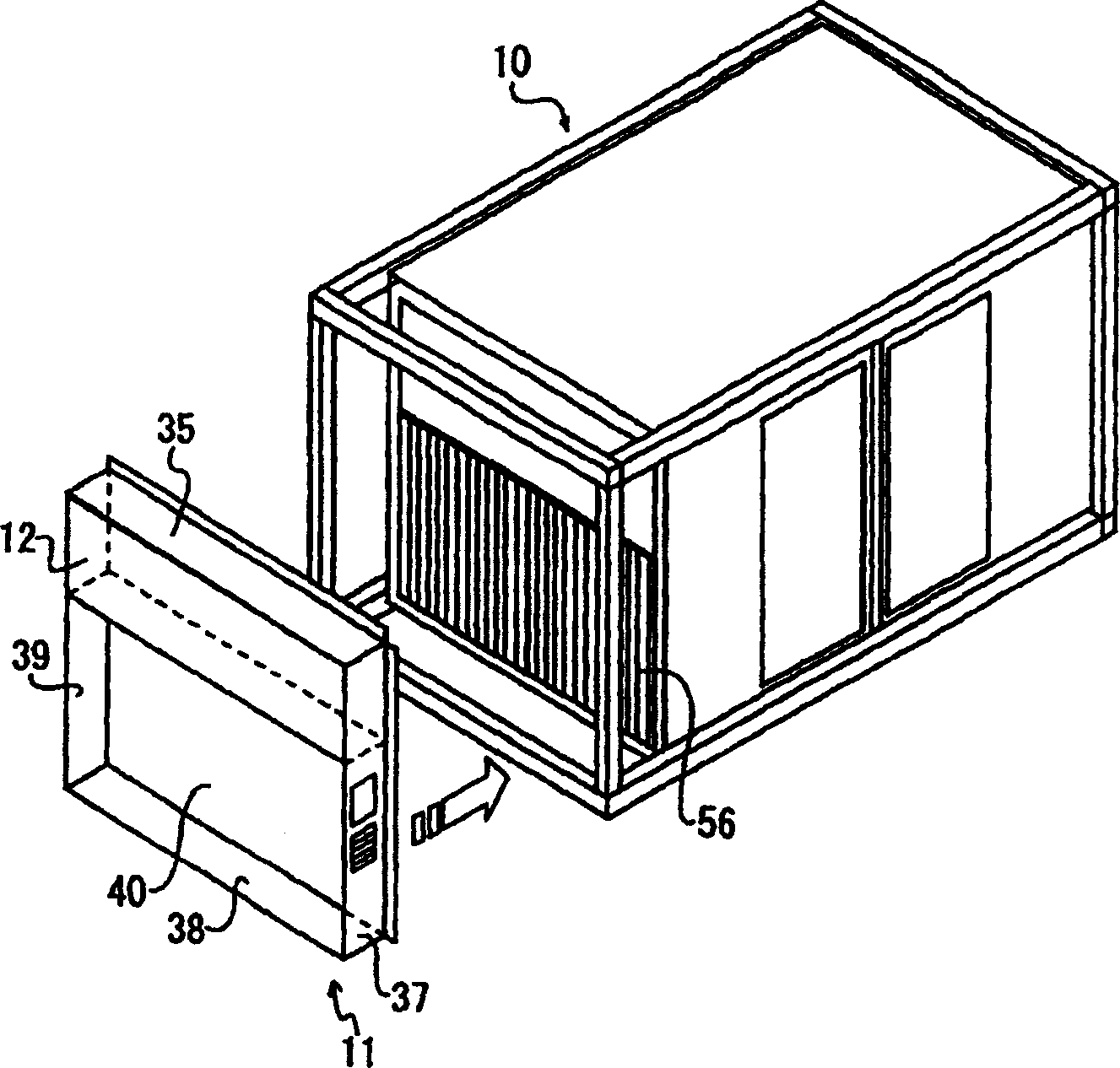
[0057] Such as figure 1 with image 3 As shown, the refrigerating device 11 is inserted into the front portion of the cuboid container 10 , and the front side is defined as the end side of the refrigerating device 11 . The housing of the refrigeration unit 11 is divided into a plurality of chambers in which various equipments are housed. Hereinafter, the left and right sides of the refrigeration apparatus 11 and the container 10 are defined in the state seen from the front. Such as figure 2 As shown, the lower part of the refrigeration device 11 is constituted by an engine room 61 on the right side, an anechoic room 62 on the left and right centers, and a fuel tank room 65 on the left side. The upper and lower central parts of the refrigerating device 11 above the chambers 61, 62, and 65 are composed of the engine cooling fan chamber 64 on the right, the monitoring chamber 54 on the upper right side directly above the engine cooling fan chamber 64, and the control chamber...


PUM


Abstract

A refrigerating device for a container mounted either in a front side or in a back side of the container comprises an engine and a fan for cooling the engine. A plurality of ventholes are formed on a plurality of wall surfaces surrounding the fan and contacting with external air, respectively, for guiding the external air into the fan. In addition, an engine fuel tank is provided. A plurality of doors are formed on a plurality of walls surrounding the fuel tank and contacting with the outside, which is open when the engine fuel tank is supplying oil. The refrigerating device further comprises a monitoring device room provided with a monitoring device for setting and displaying condition within the container and a turning mechanism for turning and supporting the monitoring device towards a plan view. The refrigerating device ensures ventilating for cooling the engine, easily supplying oil for the fuel tank, as well as easily operating of the monitoring device while arranging the container of the refrigerating device from either the longitudinal or parallel directions.

Description

technical field [0001] The present invention relates to a refrigerating device detachably mounted on the front and rear sides of a container, in particular to the structure of the refrigerating device for ensuring the ventilation of internal equipment relative to the outside and facilitating handling, and the components formed by the refrigerating device The structure of the effective cold air passage, and the compactness of the refrigeration unit. Background technique [0002] In the past, refrigerated containers were fitted with a freezer on one side called the end side. The door of the container is arranged on the side opposite to the end side of the refrigerated container. Typically, when stacking onto vans and trucks, have the end side at the front. In addition, a plurality of refrigerated containers are often loaded in tandem with the end side of each container in front, that is, the rear side (on the door side) of one container faces the end side of another containe...

Claims


Application Information

Patent Timeline
IPC IPC(8): B65D88/74B65D90/00F25D17/06
Inventor 浅越胜征相泽宏文石野忠佐藤孝康
Owner SEIREI IND CO LTD
Learn More