
Medical cryoablation catheter

A technology for ablation catheters and sheaths, applied in the medical field, can solve the problems of large cooling capacity consumption, high risk factor, and slow cooling rate, and achieve the effects of uniform cooling capacity distribution, improved safety, and control of cooling capacity dispersion

Pending Publication Date: 2020-12-08
陈湛潘
View PDF1 Cites 0 Cited by
  • Summary
  • Abstract
  • Description
  • Claims
  • Application Information

AI Technical Summary

Problems solved by technology

[0002] Patent No.: CN201520045658 discloses a cryoablation balloon catheter with a guide wire lumen. The basic principle is to block the renal artery through the balloon to block the blood flow, and then release the cold energy from the helical structure in the middle area of ​​the balloon, thereby To achieve ablation of the renal artery, although the catheter can cryoablate the renal artery, it is necessary to block the renal artery and block the blood flow to improve the freezing performance of the catheter. If the blocking time is too long, it may cause renal ischemia necrosis
[0003] Most of the existing cryoablation products are structures in which the refrigerant is directly injected into the balloon or diffused from the center of the cold source in the balloon, but the structure of directly injecting refrigerant into the balloon is likely to cause the balloon to burst, and the risk factor Too high; while the cooling rate of the structure in the balloon centered on the cold source diffuses outward is too slow, and the cooling energy consumption is too large

Method used


Image

  • Medical cryoablation catheter
  • Medical cryoablation catheter
  • Medical cryoablation catheter

Examples


Embodiment Construction

[0026] In order to make the technical solution of the present invention clearer, the present invention will be further described below in conjunction with the accompanying drawings. Any solution obtained by equivalent replacement and conventional reasoning of the technical features of the technical solution of the present invention falls within the protection scope of the present invention.

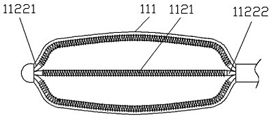
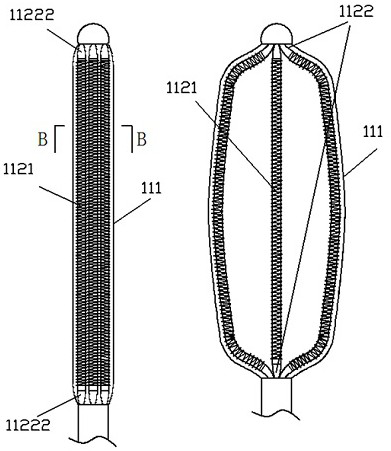
[0027] Such as figure 1 The shown medical cryoablation catheter includes a delivery unit 120 and a freezing unit 110, wherein the delivery unit 120 includes a sheath tube 121 and a circulation circuit 122 arranged axially in the sheath tube 121, and the freezing The unit 110 is set at the distal end of the sheath tube 121, that is, the leftmost end of the delivery unit 120. The freezing unit 110 includes a balloon 111 and a directional bender 1121. The distal part of the circulation loop 122 is set at the In the balloon 111, the distal end of the circulation loop 122 is fixedly connected ...


PUM


Abstract

The present invention discloses a medical cryoablation catheter and belongs to the field of medical treatment. Main points of a technical scheme are as follows: the medical cryoablation catheter mainly comprises a conveying unit and a freezing unit, the conveying unit comprises a sheathing canal and a circulation loop arranged in the sheathing canal in an axial direction, the freezing unit is arranged at a far end of the sheathing canal, the freezing unit comprises a balloon and a directional bending piece, a far end of the circulation loop is arranged in the balloon, the far end of the circulation loop is fixedly connected with a far end of the balloon, the directional bending piece is connected to the far end of the circulation loop in a sleeving mode, shape changes of the balloon drivethe directional bending piece to bend, so that distance between the circulation loop and an inner wall of the balloon is controllable; and a refrigerant can be prevented from being directly sprayed into the balloon, a cooling rate and a freezing temperature of a freezing ablation area are effectively controlled, and a freezing performance of the freezing ablation catheter is improved.

Description

technical field [0001] The invention belongs to the medical field, in particular to a medical cryoablation catheter. Background technique [0002] Patent No.: CN201520045658 discloses a cryoablation balloon catheter with a guide wire lumen. The basic principle is to block the renal artery through the balloon to block the blood flow, and then release the cold energy from the helical structure in the middle area of ​​the balloon, thereby To achieve ablation of the renal artery, although the catheter can cryoablate the renal artery, it is necessary to block the renal artery and block the blood flow to improve the freezing performance of the catheter. If the blocking time is too long, it may cause renal ischemia Sexual necrosis. [0003] Most of the existing cryoablation products are structures in which the refrigerant is directly injected into the balloon or diffused from the center of the cold source in the balloon, but the structure of directly injecting refrigerant into the...

Claims


Application Information

Patent Timeline
Patent Type & Authority Applications(China)
IPC IPC(8): A61B18/02
CPCA61B18/02A61B2018/00577A61B2018/0212
Inventor 陈湛潘
Owner 陈湛潘
Learn More