Refrigerating device

A technology of refrigeration device and decompression device, which is applied in refrigerators, refrigeration components, refrigeration and liquefaction, etc., to achieve high refrigeration capacity and improve decompression effect

Active Publication Date: 2009-04-15
SANYO ELECTRIC CO LTD
View PDF1 Cites 10 Cited by
  • Summary
  • Abstract
  • Description
  • Claims
  • Application Information

AI Technical Summary

Problems solved by technology

However, when the refrigerating device is sufficiently cooled, there is a problem that a large amount of liquefied surplus refrigerant is generated in the refrigerating device

Method used


Image

  • Refrigerating device
  • Refrigerating device
  • Refrigerating device

Examples


Embodiment 1

[0039] (1) Freezing device applicable to the present invention

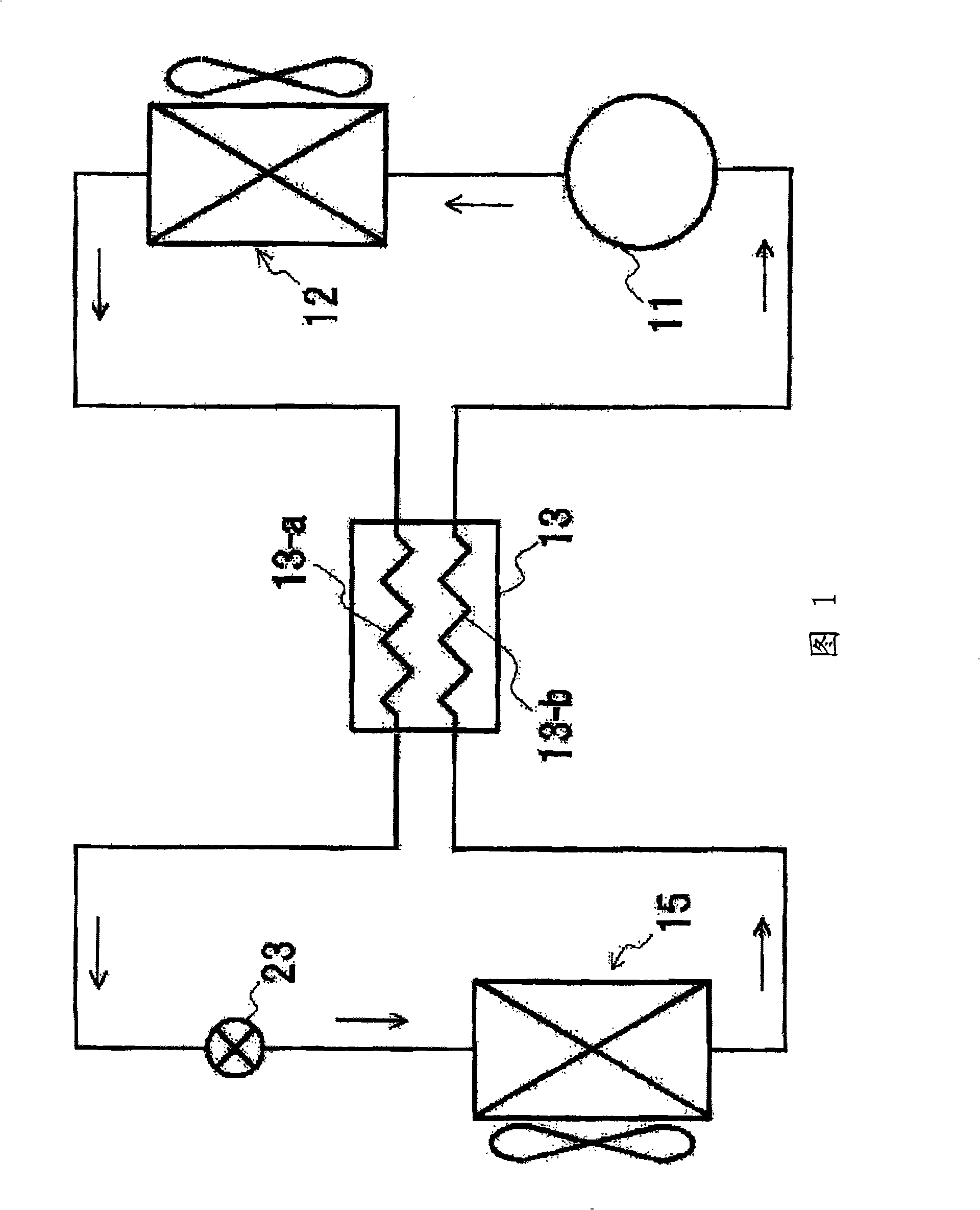
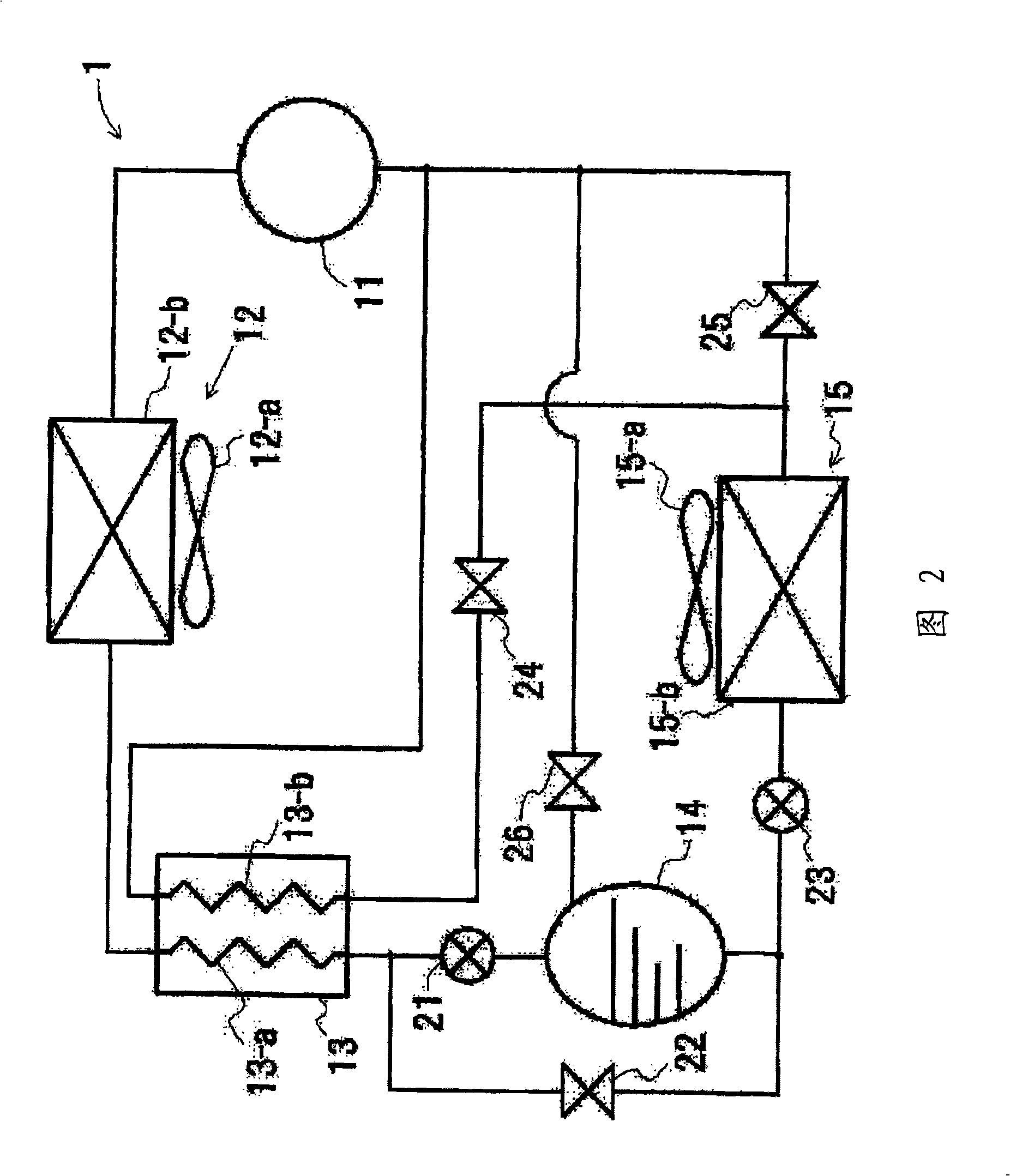
[0040] Fig. 2 is a refrigerant circuit 1 of a refrigeration system according to an embodiment of the present invention. In the drawings, reference numeral 11 denotes a compressor, 12 denotes a gas cooler, 13 denotes a cascade heat exchanger (internal heat exchanger), 14 denotes a liquid receiver, 15 denotes an evaporator, and 21 denotes a second expansion valve (reduction pressure device), 22, 24, 25 and 26 represent solenoid valves (on-off valves), and 23 represent the first expansion valve.

[0041] In addition, the compressor 11 is a single stage or a multi-stage compressor with two or more stages. Since the refrigerant is in a subcritical state on the low-pressure side of the compressor 11 and the output refrigerant is in a supercritical state, the entire refrigeration system is in a transition critical state. As a refrigerant having the above properties, carbon dioxide is used in this embodiment.

[0042]...

Embodiment 2

[0070] Next, other embodiments of the present invention will be described in detail based on FIGS. 7 to 11 .

[0071] (5) Freezing device applicable to the present invention

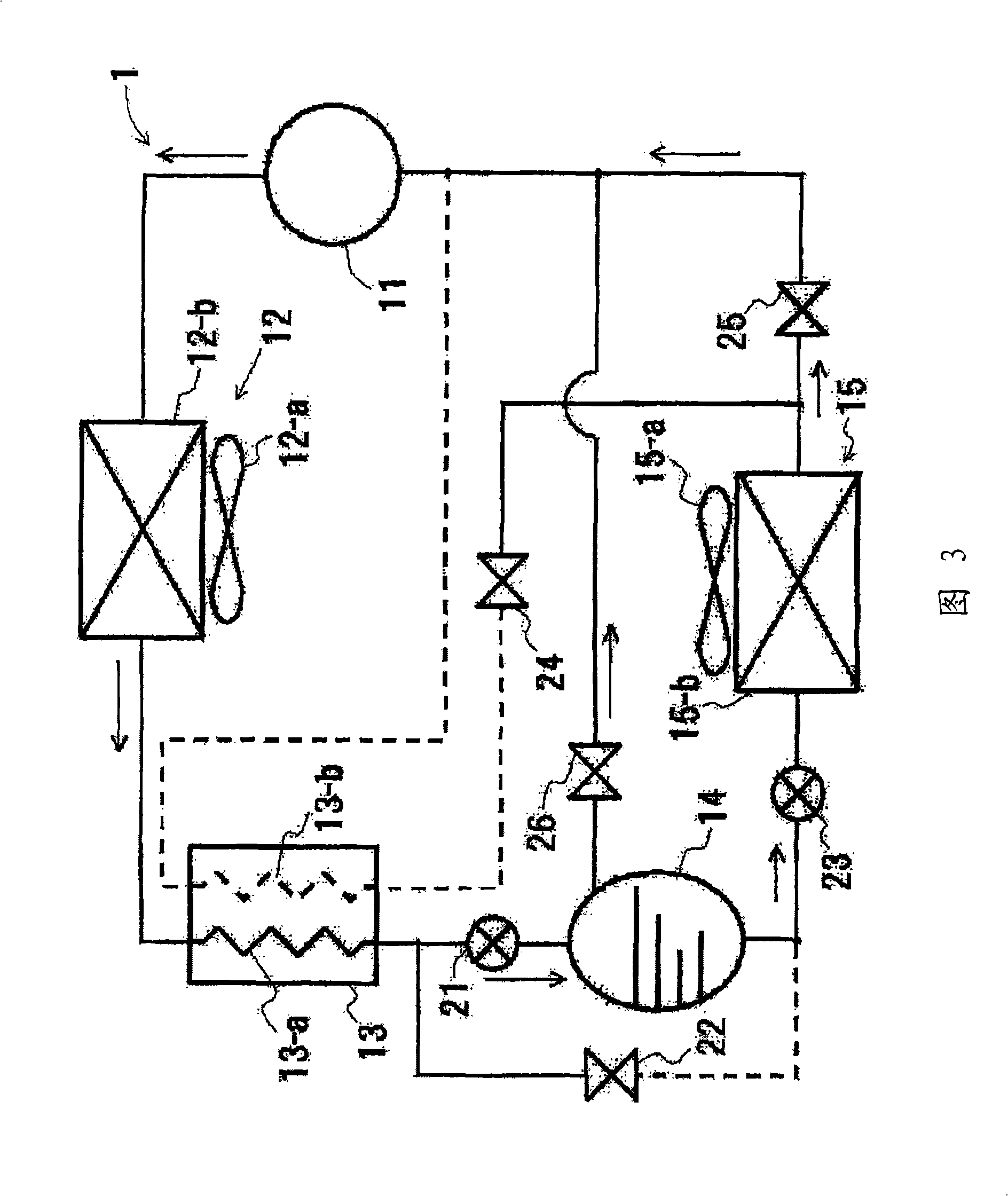
[0072] Fig. 7 shows a refrigerant circuit 1 of a refrigeration system to which another embodiment of the present invention is applied. In the drawings, reference numeral 11 denotes a compressor, 12 denotes a gas cooler, 13 denotes a cascade heat exchanger (internal heat exchanger), 14 denotes a liquid receiver, 15 denotes an evaporator, and 21 denotes a second expansion valve (reduction pressure device), 22, 24, 25 and 26 represent solenoid valves (on-off valves), and 23 represent the first expansion valve.

[0073] The compressor 11 is a multi-stage compressor of two or more stages capable of sucking refrigerant not only from the low-pressure part but also from the intermediate-pressure part. Since the refrigerant is in a subcritical state on the low-pressure side of the compressor 11 and the output r...


PUM


Abstract

A freezing apparatus using such a coolant as will take a supercritical state when discharged from a compressor is troubled by a problem that the charge of the coolant has to be increased to quicken the cooling operation, because of shortage of the freezing power. Another problem is that an excess coolant is much produced in a coolant circuit when the freezing apparatus is sufficiently cooled. Provided is a coolant circuit, in which a compressor, a gas cooler, a first pressure reducing device and an evaporator are sequentially piped and connected in an annular shape. The coolant circuit comprises a second pressure reducing device and a liquid receiver between the gas cooler and the first pressure reducing device, and the liquid receiver and the suction port of the compressor are piped and connected. The opening degree of the second pressure reducing device is controlled according to the pressure difference between the discharge side pressure and the suction side pressure of the compressor, so that the circulation rate of the coolant can be adjusted by increasing the coolant circulation rate in case the freezing ability is short and by reserving the excess coolant in the liquid receiver in case the freezing ability is excessive.

Description

technical field [0001] The present invention relates to a refrigerating device having a refrigerant circuit in which a compressor, a gas cooler, a decompression device, an evaporator, etc. are connected by piping, and using carbon dioxide (CO 2 ) and other natural refrigerants. Background technique [0002] In the past, Freon-based refrigerants were used in refrigeration equipment, but due to the problems of Freon depleting the ozone layer and causing the global warming effect, its use began to be strictly limited. As an alternative refrigerant, CO 2 The development of refrigeration equipment for natural refrigerants such as natural refrigerants or hydrocarbons is underway. [0003] Among the above-mentioned natural refrigerants, refrigerants that are particularly expected as next-generation refrigerants are expected to be non-flammable, unlike flammable hydrocarbons or toxic ammonia, even though they have a low global warming coefficient. And it is non-toxic, so it is fri...

Claims


Application Information

Patent Timeline
Patent Type & Authority Applications(China)
IPC IPC(8): F25B1/00F25B43/00
CPCF25B2400/23F25B2400/13F25B2309/061
Inventor 三原一彦
Owner SANYO ELECTRIC CO LTD
Why Eureka
Try Eureka