
Filter water distribution structure and filter

A technology of filter and water distribution cap, which is applied in the field of filter water distribution structure and filter, which can solve the problems that affect the user's use efficiency, cannot meet the drinking requirements, and the filter is damaged under pressure, so as to achieve simple structure and avoid impact , the effect of speeding up the flow rate

Active Publication Date: 2018-07-20
JINGSHUITANG TECH CONSULTING SERVICE BEIJING CO LTD
View PDF8 Cites 2 Cited by
  • Summary
  • Abstract
  • Description
  • Claims
  • Application Information

AI Technical Summary

Problems solved by technology

At present, tap water, the main source of drinking water, cannot meet the drinking requirements due to the aggravation of water pollution, the problem of disinfection by-products produced by chlorine sterilization in the production process, and the secondary pollution of the pipe network.
Moreover, the bottled water used in large quantities in the past is prone to secondary pollution during the sealing, storage and distribution process. In order to ensure the freshness and cleanness of the water quality, people have higher and higher requirements for water purification equipment.
[0003] By directly passing a filter between the water inlet and outlet of the water flow, the filter material set in the filter is used to remove heavy metal ion pollution, sediment, rust, micro-pollutant organic matter, etc. in the water, generally to ensure the water quality of the filtered water flow , the apertures of the water inlet and outlet holes on the filter will not be set too large, which will inevitably cause the flow rate of the water to slow down, which will affect the user's use efficiency, and the water flow introduced into the filter will generate a certain amount of water. Pressure, the collected water flows directly into the filter from the smaller water inlet hole, and the water pressure is too high, which will cause the filter to be damaged under pressure.

Method used


Image

  • Filter water distribution structure and filter
  • Filter water distribution structure and filter
  • Filter water distribution structure and filter

Examples


Embodiment Construction

[0042] In order to more clearly illustrate the embodiments of the present invention or the technical solutions in the prior art, the specific implementation manners of the present invention will be described below with reference to the accompanying drawings. Obviously, the accompanying drawings in the following description are only some embodiments of the present invention, and those skilled in the art can obtain other accompanying drawings based on these drawings and obtain other implementations.

[0043] In order to make the drawing concise, each drawing only schematically shows the parts related to the present invention, and they do not represent the actual structure of the product. In addition, to make the drawings concise and easy to understand, in some drawings, only one of the components having the same structure or function is schematically shown, or only one of them is marked. Herein, "a" not only means "only one", but also means "more than one".

[0044] In the pri...


PUM


Abstract

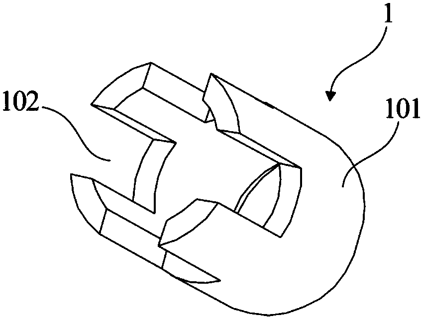
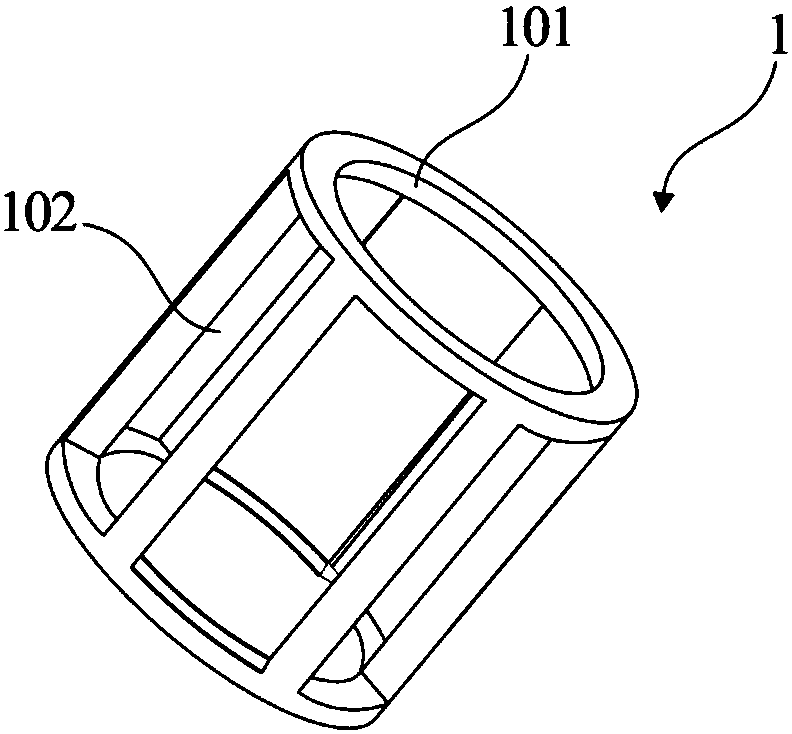
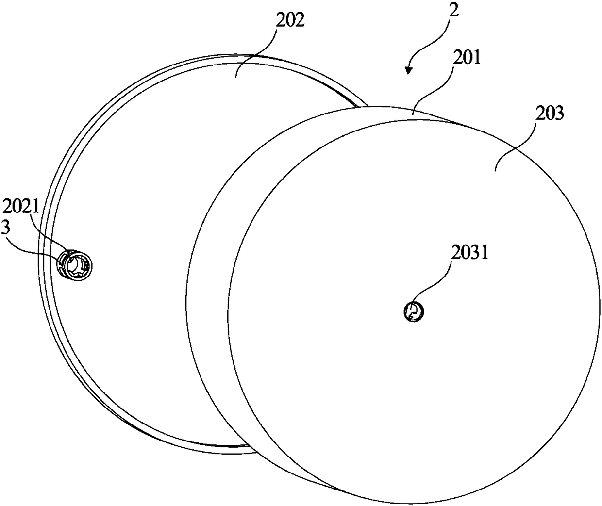
The invention provides a water distribution structure of a filter. The water distribution structure is a tubular body structure formed by at least one side plate in an enclosing mode; the two ends of the tubular body structure are communicated with each other to be used for flowing of water flow, and the tube wall of the tubular body structure is provided with first through holes. The invention further provides the filter which comprises at least one material filtering frame, the material filtering frames are of a barrel structure, and the top and the bottom of each material filtering frame are provided with material filtering covers respectively; the upper material filtering cover of each material filtering frame is provided with a water outlet hole, and the lower material filtering cover of each corresponding material filtering frame is provided with a water inlet hole, wherein the water distribution structure of the filter is arranged at the water outlet hole and / or the water inlet hole. According to the water distribution structure, the outflow area of the water flow can be increased, so that the flow velocity of the water flow is increased; the water flow can flow out in the different directions, so that water pressure can be reduced; the structure is simple, installation is convenient, and the production cost is low.

Description

technical field [0001] The invention relates to the field of water purifier equipment, in particular to a filter water distribution structure and a filter. Background technique [0002] With the improvement of economic conditions and the improvement of living standards, people have higher requirements for drinking water quality. At present, tap water, the main source of drinking water, cannot meet the drinking requirements due to the aggravation of water pollution, the problem of disinfection by-products produced by chlorine sterilization in the production process, and the secondary pollution of the pipe network. Moreover, the bottled water used in large quantities is prone to secondary pollution during the sealing, storage and distribution process. In order to ensure the freshness and cleanness of the water quality, people have higher and higher requirements for water purification equipment. [0003] By directly passing a filter between the water inlet and outlet of the wa...

Claims


Application Information

Patent Timeline
Patent Type & Authority Patents(China)
IPC IPC(8): B01D24/16B01D24/40
CPCB01D24/16B01D24/40
Inventor 唐建星
Owner JINGSHUITANG TECH CONSULTING SERVICE BEIJING CO LTD
Learn More