Automatic natural rubber collecting device for rubber

A natural rubber, automatic collection technology, applied in the fields of application, forestry, agriculture, etc., can solve the problems of heavy physical burden, low work efficiency, troublesome collection of natural rubber, etc.

Inactive Publication Date: 2021-06-18
哈尔滨市阿城区胜达建筑材料厂
View PDF0 Cites 0 Cited by
  • Summary
  • Abstract
  • Description
  • Claims
  • Application Information

AI Technical Summary

Problems solved by technology

[0002] In terms of comprehensive performance, synthetic rubber is not as good as natural rubber. At present, heavy tires such as aircraft tires, engineering machinery tires and off-road tires used in the world are basically made of natural rubber, and the collection of natural rubber is very troublesome. The old-fashioned collection method Manually cut grooves on the rubber tree to let the juice flow out and collect it through the V-shaped plate and the container, which not only has low work efficiency, but also has a large physical burden

Method used


Image

  • Automatic natural rubber collecting device for rubber
  • Automatic natural rubber collecting device for rubber
  • Automatic natural rubber collecting device for rubber

Examples


specific Embodiment approach 1

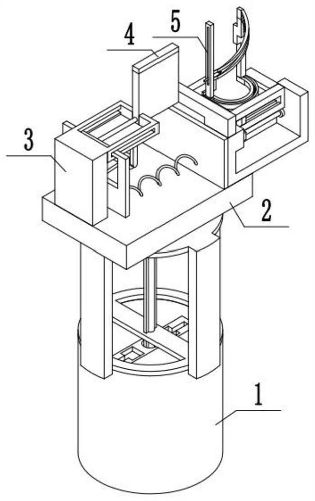
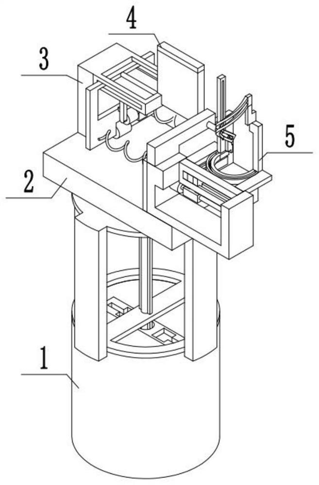
[0038] Combine below figure 1 , 2 Description of this embodiment, a natural rubber automatic collection device for rubber, including a height adjustment device 1, a mounting seat plate 2, a drainage tube insertion device 3, a drainage tube placement device 4 and a rubber tree cutting device 5, the height adjustment device 1 is fixedly installed with an installation seat plate 2, and a drainage tube driving device 3 is installed on the installation seat plate 2, and a drainage tube placement device 4 is fixedly installed on the drainage tube insertion device 3, and the drainage tube placement device 4 is fixedly installed on the rubber tree. On the cutting device 5, the rubber tree cutting device 5 is fixedly connected with the drainage tube driving device 3.

specific Embodiment approach 2

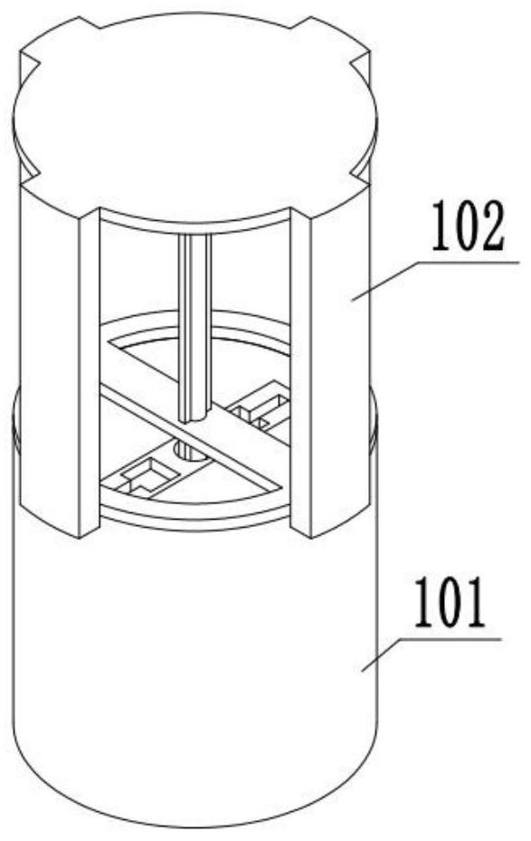
[0040] Combine below image 3 , 4 , 5, 6, 7, 8, and 9 illustrate this embodiment, and this embodiment will further explain Embodiment 1. The height adjustment device 1 includes a drive mechanism 101, a support upper frame body 102, and a support upper frame is installed on the drive mechanism 101. Body 102;

[0041] The driving mechanism 101 includes a fixed sleeve 103, an upper cover plate 104, a power motor A105, a feed screw 106, a support carriage 107, and a fixed slide plate 108. An upper cover plate 104 is fixedly installed above the fixed sleeve 103, and the power The motor A105 is fixedly installed on the fixed sleeve 103, the output end of the power motor A105 is equipped with a feed screw 106, the feed screw 106 is threaded with a support carriage 107, and the support carriage 107 is slidably installed on the fixed slide plate 108, The two ends of the support carriage 107 are slidably mounted on the fixed sleeve 103;

[0042] The support upper frame body 102 inclu...

specific Embodiment approach 3

[0044] Combine below Figure 10 , 11 Describe this embodiment, this embodiment will further explain Embodiment 1, the described drainage tube driving device 3 includes a fixed support plate 301, a spring A302, a rod driving plate 303, support wheels 304, an L-shaped frame 305, and a power motor B306, the fixed frame body 307, the drainage pipe rod 308, the fixed support plate 301 is fixedly installed on the installation seat plate 2, the two ends of the spring A302 are respectively fixedly installed on the fixed support plate 301 and the rod driving plate 303, and the rod drives the The plate 303 is fixedly installed with a drainage tube driving rod 308, and the supporting wheels 304 are movably installed on the driving board 303 for driving the rod. The type frame 305 is installed on the output end of the power motor B306, and the power motor B306 is fixedly installed on the fixed frame body 307, and the fixed frame body 307 is slidably installed with a rod driving plate 303...


PUM


Abstract

The invention relates to a natural rubber collecting device, in particular to an automatic natural rubber collecting device for rubber, which comprises a height adjusting device, a mounting seat plate, a drainage tube driving device, a drainage tube placing device and a rubber tree cutting device. The mounting seat plate is fixedly mounted above the height adjusting device. The drainage tube driving device is mounted on the mounting seat plate, a drainage tube placing device is fixedly mounted on the drainage tube driving device, the drainage tube placing device is fixedly mounted on the rubber tree cutting device, and the rubber tree cutting device is fixedly connected with the drainage tube driving device. The device can automatically cut grooves in a rubber tree, so that the labor force is liberated. The device can automatically drive a drainage tube into the rubber tree, the drive position is more accurate than that of manual drive, meanwhile, labor force is liberated, the height of the device can be adjusted, and the high-quality part of the rubber tree can be selected for rubber collection.

Description

technical field [0001] The invention relates to a natural rubber collecting device, in particular to an automatic natural rubber collecting device for rubber. Background technique [0002] In terms of comprehensive performance, synthetic rubber is not as good as natural rubber. At present, heavy tires such as aircraft tires, engineering machinery tires and off-road tires used in the world are basically made of natural rubber, and the collection of natural rubber is very troublesome. The old-fashioned collection method Manually cutting grooves on the rubber tree to allow the juice to flow out and collect it through the V-shaped plate and the container, not only the work efficiency is low, but also there will be a greater physical burden. Contents of the invention [0003] The technical problem that the present invention mainly solves is to provide a kind of natural rubber automatic collection device for rubber, 1. this device can automatically cut grooves on the rubber tree...

Claims


Application Information

Patent Timeline
Patent Type & Authority Applications(China)
IPC IPC(8): A01G23/10A01G23/12A01G23/14
CPCA01G23/10A01G23/12A01G23/14
Inventor 姜胜付
Owner 哈尔滨市阿城区胜达建筑材料厂
Why Eureka
Try Eureka