A spinal joint decompression system and method of use thereof

A joint and spine technology, applied in the field of spine joint decompression system, can solve problems such as low control accuracy, insufficient treatment, lack of automatic control, etc., to avoid excessive traction, improve decompression effect, and ensure safety sexual effect

Inactive Publication Date: 2019-01-08
THE AFFILIATED HOSPITAL OF QINGDAO UNIV
View PDF8 Cites 2 Cited by
  • Summary
  • Abstract
  • Description
  • Claims
  • Application Information

AI Technical Summary

Problems solved by technology

In today's highly modernized development, it is very necessary to use modern measurement and control technology to accurately and scientifically perform spinal decompression. The control accuracy of the system is not high, and the degree of automatic control is still lacking. In addition, the current existing technology lacks the modular design of the decompression system, which is inconvenient for the function combination and expansion of the system.
In particular, the control of the bed surface angle of the traction bed and the working state of the pressure mechanism applied to the patient's neck, waist and ankles cannot be accurately controlled, and it often occurs that the force value applied to the patient's body is not enough to achieve treatment. effect, or excessive force exerted on the patient's body, causing the patient's pain transition to create a dangerous phenomenon
[0004] In order to solve the above problems, the patent with the existing patent notification number CN104306132A discloses a decompression system, but the effect of this system is not good when the patient's body is pulled. In view of this problem, a spinal joint is now provided Pressure reducing system and method of use

Method used


Image

  • A spinal joint decompression system and method of use thereof
  • A spinal joint decompression system and method of use thereof

Examples


Embodiment Construction

[0019] The following will clearly and completely describe the technical solutions in the embodiments of the present invention with reference to the accompanying drawings in the embodiments of the present invention. Obviously, the described embodiments are only some, not all, embodiments of the present invention. Based on the embodiments of the present invention, all other embodiments obtained by persons of ordinary skill in the art without making creative efforts belong to the protection scope of the present invention.

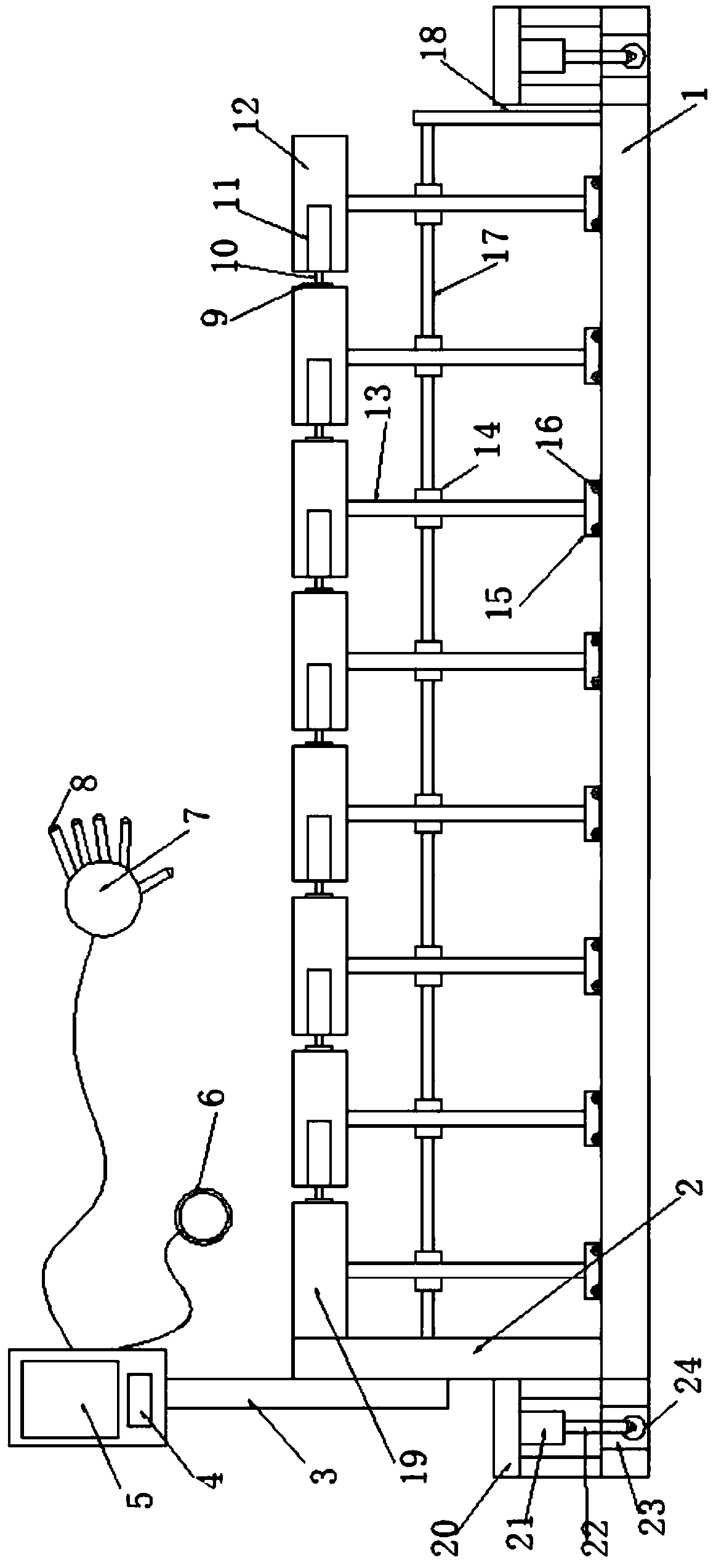
[0020] see Figure 1~2 , in an embodiment of the present invention, a spinal joint decompression system and its use method include a base 1, a decompression bed 19 is arranged above the base 1, and the left end of the decompression bed 19 is connected and fixed to the fixed plate 2, and the fixed plate 2 Vertically fixed on the upper left side of the base 1, the upper end of the fixing plate 2 is connected to a control panel through a support frame 3, a displa...


PUM


Abstract

The invention discloses system for decompress spinal joint and a method for using that same are disclose, including the base. A pressure reducing bed is arranged above the base. A left end of that decompression bed is connected with a fixing plate and fixed. A fixed plate is vertically fixed on that upper left side of the base. An upper end of that fix plate is connected with a control panel through a support frame. The control panel is provided with a display screen and a processor electrically connected with the display screen. A processor is electrically connected to the decompression detection module. A decompression detection module includes a patient state monitoring module for detecting a heart rate state of a patient. A finger pressure monitoring module for detecting finger pressure of a massage worker and a traction force monitoring module for detecting a magnitude of traction force on a spine. The processor is also electrically connected with an emergency button module, and the patient state monitoring module comprises a heart rate bracelet. The invention has the advantages of simple structure, reasonable structure, convenient handling, and the decompression mode eliminates the drawbacks existing in the existing device and improves the decompression effect.

Description

technical field [0001] The invention relates to the technical field of medical equipment, in particular to a spinal joint decompression system and its application method. Background technique [0002] Modern people often sit in front of the computer for a long time due to work, study and entertainment. There are more and more patients with cervical and lumbar diseases. Statistics show that in China, the incidence of cervical and lumbar diseases is as high as 25%, and it is increasing year by year. Hundreds of millions of people are troubled by symptoms such as pain and limb numbness caused by cervical spondylosis. For patients, the treatment method that can relieve and cure the disease without surgery is of course the most ideal method. [0003] Since ancient times, China has used massage methods to treat bruises, and gradually developed and formed the discipline of massage in traditional Chinese medicine. Massage belongs to the category of external treatment of traditional...

Claims


Application Information

Patent Timeline
Patent Type & Authority Applications(China)
IPC IPC(8): A61F5/042A61B5/024
CPCA61B5/02438A61B5/681A61F5/042
Inventor 相宏飞沈娜娜陈伯华
Owner THE AFFILIATED HOSPITAL OF QINGDAO UNIV
Why Eureka
Try Eureka