Product suction detection structure for automatic dust collector detection line
An automatic detection and structure detection technology, which is applied in the testing of machine/structural components, measuring fluid pressure, instruments, etc., can solve the problems of high equipment operation, large floor space, troublesome operation, etc., and achieve low manufacturing cost and compact structure , the effect of convenient operation
- Summary
- Abstract
- Description
- Claims
- Application Information
AI Technical Summary
Problems solved by technology
Method used
Image
Examples
Embodiment 1
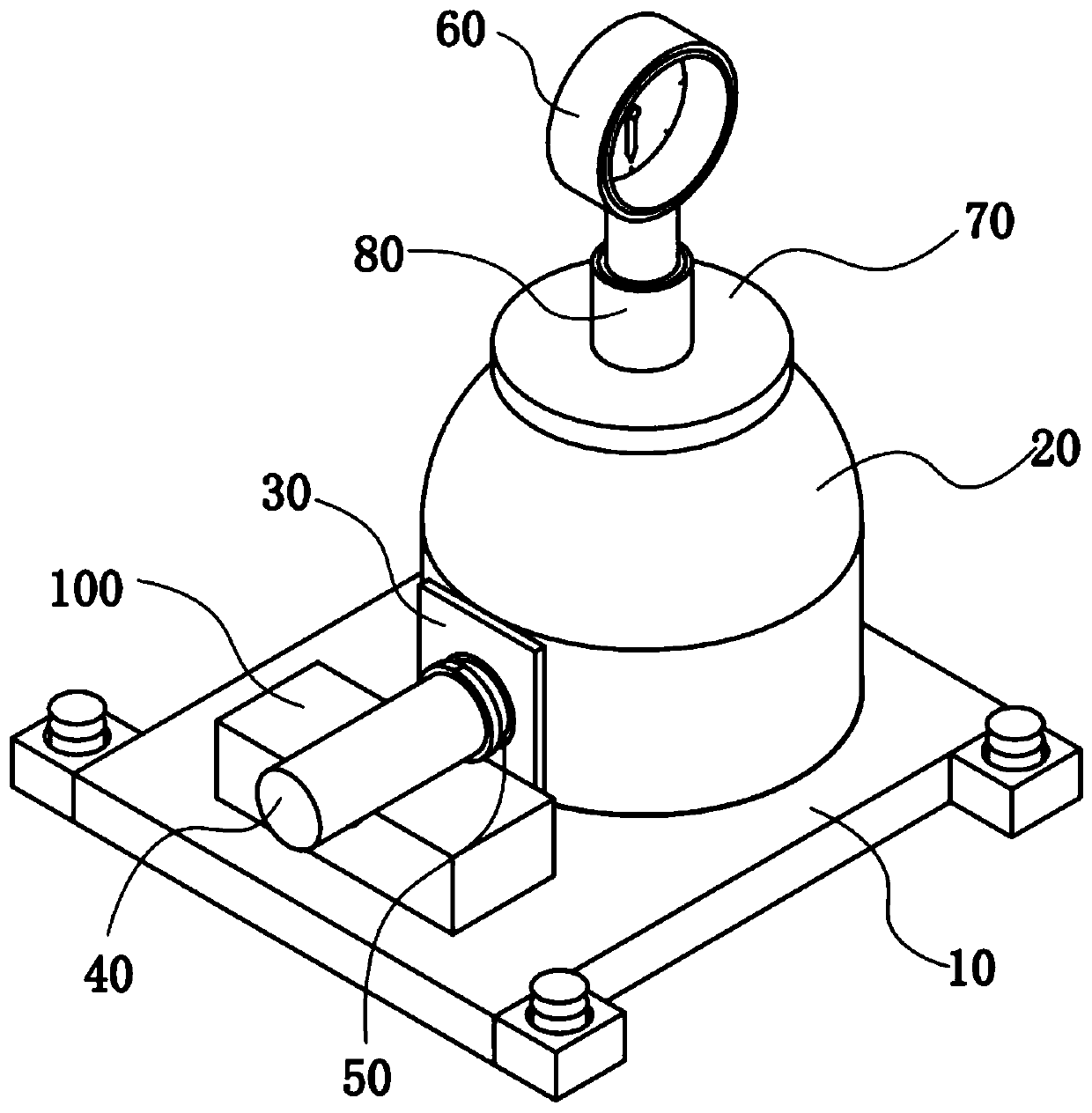
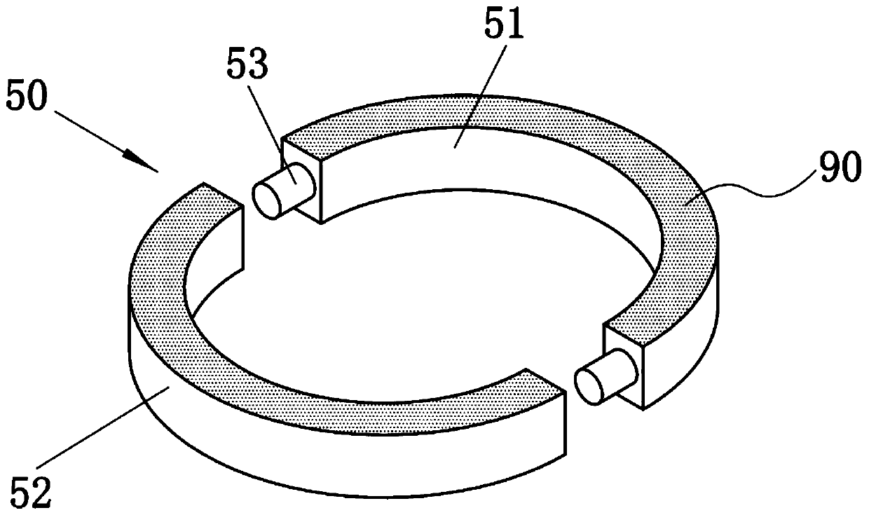
[0033] A vacuum cleaner automatic detection line product suction detection structure, which includes a mounting base 10, a vacuum cover 20, a vacuum cleaner suction pipe 40, a sealing structure 50 and a negative pressure gauge 60, and the vacuum cover 20 is arranged on the top of the mounting base 10 , and the outer side of the bottom of the vacuum cover 20 is fixed with a gasket 30, the middle part of the gasket 30 is provided with a through hole 31, and the inner end of the suction pipe 40 of the vacuum cleaner is connected with the through hole 31. The sealing structure 50 is sleeved on the inner end of the suction pipe 40 of the vacuum cleaner, and the sealing structure 50 is magnetically connected to the gasket 30 , and the negative pressure gauge 60 is disposed above the vacuum cover 20 .
[0034] In this embodiment, the top of the vacuum cover 20 is fixed with a flange 70, and the top of the flange 70 is fixed with a diaphragm seat 80, and the negative pressure gauge 60 ...
Embodiment 2
[0040] A vacuum cleaner automatic detection line product suction detection structure, which includes a mounting base 10, a vacuum cover 20, a vacuum cleaner suction pipe 40, a sealing structure 50 and a negative pressure gauge 60, and the vacuum cover 20 is arranged on the top of the mounting base 10 , and the outer side of the bottom of the vacuum cover 20 is fixed with a gasket 30, the middle part of the gasket 30 is provided with a through hole 31, and the inner end of the suction pipe 40 of the vacuum cleaner is connected with the through hole 31. The sealing structure 50 is sleeved on the inner end of the suction pipe 40 of the vacuum cleaner, and the sealing structure 50 is magnetically connected to the gasket 30 , and the negative pressure gauge 60 is disposed above the vacuum cover 20 .
[0041] In this embodiment, the top of the vacuum cover 20 is fixed with a flange 70, and the top of the flange 70 is fixed with a diaphragm seat 80, and the negative pressure gauge 60 ...
Embodiment 3
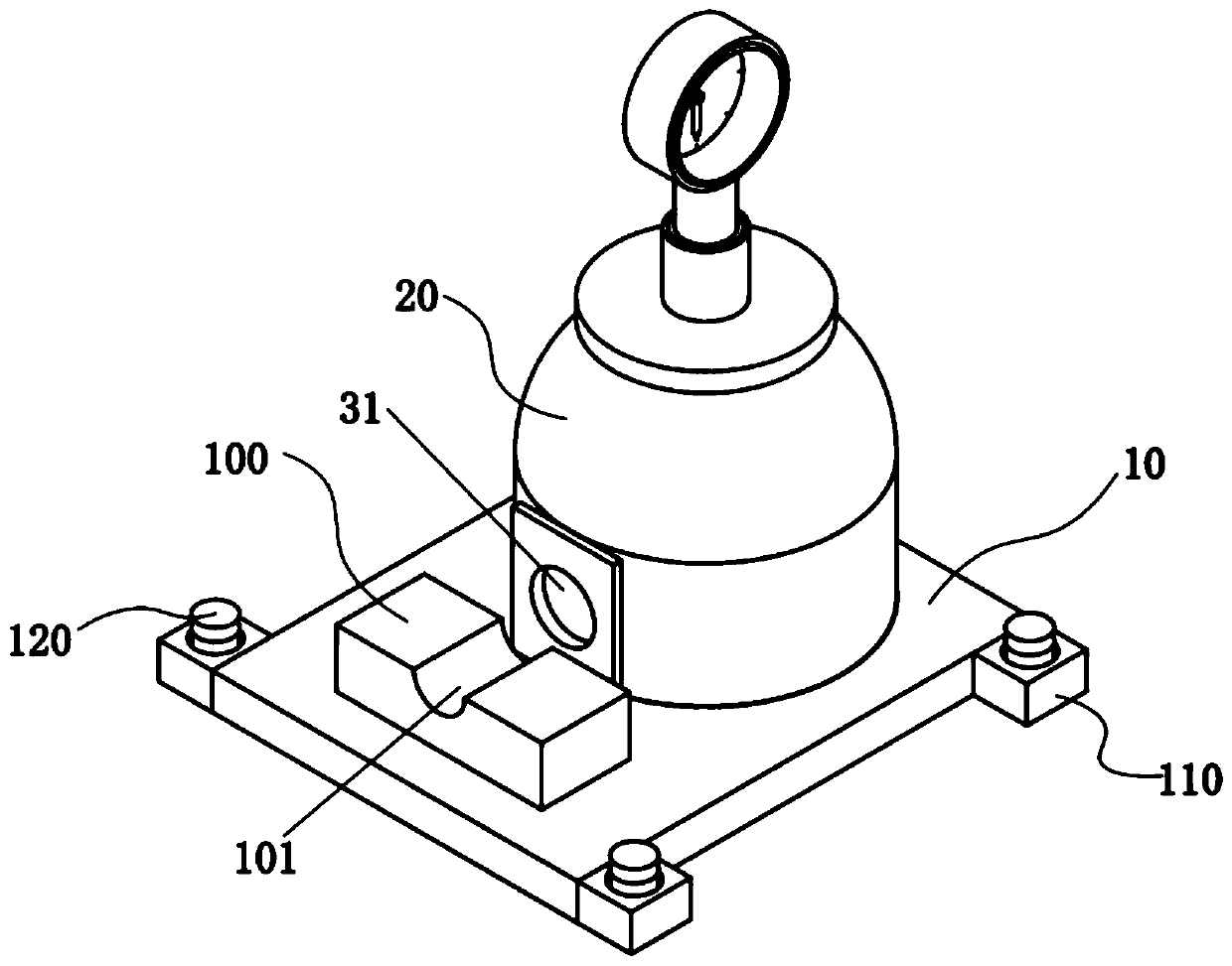
[0047] Such as image 3As shown, on the basis of Embodiment 1 or Embodiment 2, the top of the installation base 10 is also provided with a base 100, the base 100 is located outside the vacuum cover 20, and the top of the base 100 A slot 101 is provided, and the lower part of the suction pipe 40 of the vacuum cleaner is located in the slot 101, which is convenient for supporting the suction pipe 40 of the vacuum cleaner and avoids bending of the suction pipe 40 of the vacuum cleaner, which may cause a decrease in detection accuracy.
PUM
 Abstract
Description
Claims
Application Information
 - R&D
- Intellectual Property
- Life Sciences
- Materials
- Tech Scout
- Unparalleled Data Quality
- Higher Quality Content
- 60% Fewer Hallucinations
Browse by: Latest US Patents, China's latest patents, Technical Efficacy Thesaurus, Application Domain, Technology Topic, Popular Technical Reports.
© 2025 PatSnap. All rights reserved.Legal|Privacy policy|Modern Slavery Act Transparency Statement|Sitemap|About US| Contact US: help@patsnap.com


