
Dust cleaning method and cleaning equipment

A technology for cleaning equipment and cleaning methods, which is applied to the installation of cleaning equipment, cleaning machinery, and electrical equipment, and can solve problems such as the influence of vacuum cleaner suction

Pending Publication Date: 2021-02-19
PUPPY ELECTRONICS APPLIANCES INTERNET TECH (BEIJING) CO LTD
View PDF0 Cites 1 Cited by
  • Summary
  • Abstract
  • Description
  • Claims
  • Application Information

AI Technical Summary

Problems solved by technology

Because particles such as hair and paper are prone to generate static electricity after contacting the filter body, hair, paper and other particles will cover the surface of the filter body, thereby affecting the suction of the vacuum cleaner.

Method used


Image

  • Dust cleaning method and cleaning equipment
  • Dust cleaning method and cleaning equipment
  • Dust cleaning method and cleaning equipment

Examples


Embodiment Construction

[0033] The present application will be described in further detail below in conjunction with the accompanying drawings and specific embodiments. It should be understood that the specific embodiments described here are only used to explain the present application, and are not intended to limit the present application. In the description of the present invention, it should be noted that the terms "upper", "lower", "left", "right", "front", "rear", "inner", "outer" and the like indicate directions or positions The relationship is based on the orientation or positional relationship shown in the drawings, or the orientation or positional relationship that the inventive product is usually placed in use, and is only for the convenience of describing the present invention and simplifying the description, rather than indicating or implying the referred device or Elements must have certain orientations, be constructed and operate in certain orientations, and therefore should not be cons...


PUM


Abstract

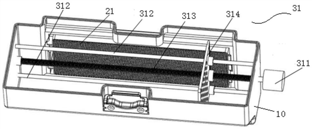
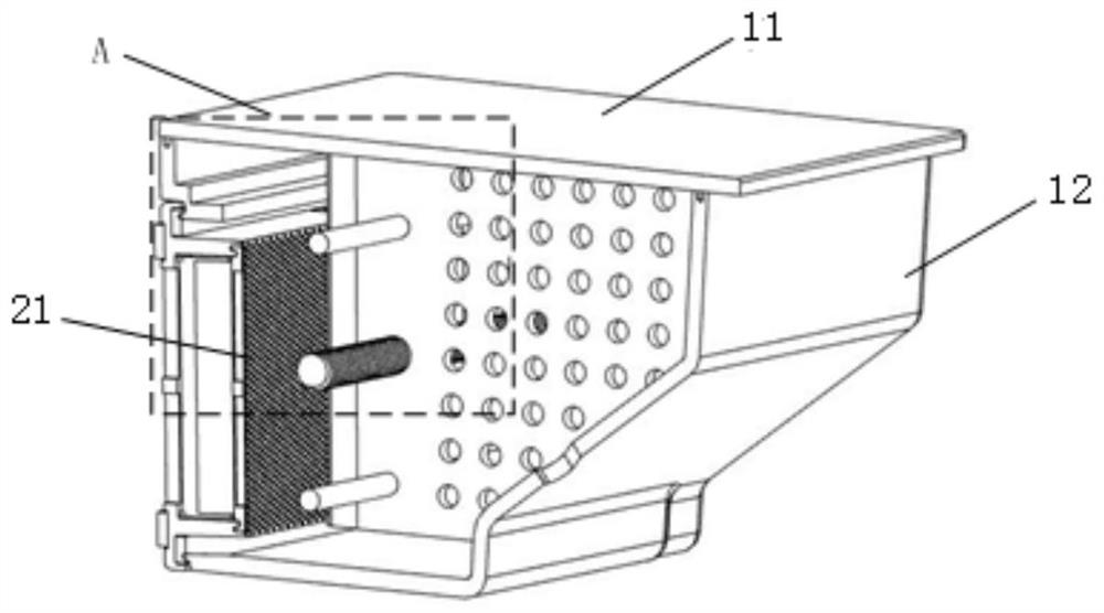
The invention relates to cleaning equipment, which comprises a main machine, a dust collecting component, an air suction motor, a filtering assembly and a cleaning assembly, wherein the air suction motor and the dust collecting component are both installed on the main machine, the filtering assembly is installed in the dust collecting component, the cleaning assembly comprises a movable plate bodyarranged in the dust collecting component, and the movable plate body can move on the surface of the filtering assembly. The invention further relates to a dust cleaning method for the cleaning equipment. The dust cleaning method comprises the steps of: detecting and acquiring a gas flow value a of an air outlet end of the filtering assembly or an air inlet end of the air suction motor; detectingthe current dust weight in the dust collecting component, and acquiring a gas flow value b corresponding to the current dust weight; and if the gas flow value a is smaller than the gas flow value b,generating an air duct blocking signal, and controlling the movable plate body in the dust collecting component to move on the surface of the filtering assembly by means of the control assembly. Through adopting the cleaning equipment and the dust cleaning method, dust can be prevented from covering the surface of the filter screen body and influencing the suction force.

Description

technical field [0001] The invention relates to the technical field of cleaning equipment, in particular to a dust cleaning method and cleaning equipment. Background technique [0002] The cleaning equipment includes the host, dust collection components, suction motor and filter components. The dust-laden fluid is sucked in from the suction port through the high-speed rotation of the suction motor, and the dust enters the dust collection component, and is filtered by the filter assembly. Wherein, the filter mesh body in the dust collection component is used to filter particulate matter such as hair and paper pieces in the dust-laden fluid. Since hair, paper pieces and other particles are prone to generate static electricity after contacting the filter body, the hair, paper pieces and other particles will cover the surface of the filter body, thereby affecting the suction of the vacuum cleaner. Contents of the invention [0003] In order to solve the above-mentioned probl...

Claims


Application Information

Patent Timeline
Patent Type & Authority Applications(China)
IPC IPC(8): A47L11/40A47L11/24A47L9/20A47L9/28A47L9/00
CPCA47L9/00A47L9/20A47L9/281A47L11/24A47L11/4013A47L11/4033
Inventor 檀冲沈荻
Owner PUPPY ELECTRONICS APPLIANCES INTERNET TECH (BEIJING) CO LTD
Learn More